Einleitung
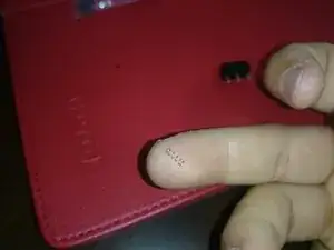
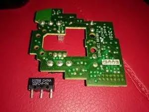
Diese Anleitung zeigt, wie der Mikroschalter Omron D2FC-F-7N unter der linken/rechten Maustaste der Logitech G700/G700s ausgetauscht wird.
Werkzeuge
Ersatzteile
-
-
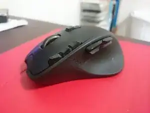
Diese Logitech G700 leistete sieben Jahre lang treue Dienste. Nun ist ein Mikroswitch kaputt gegangen.
-
-
-
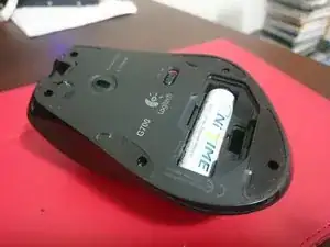
Beginne damit, die Maus auszuschalten und die hintere Batterieabdeckung und den Akku der Maus zu entfernen.
-
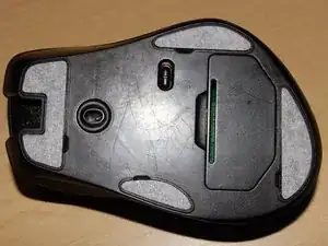
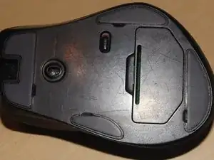
Entferne dann die Teflon-"Füße" der Maus, um zu den fünf (5) Schrauben zu gelangen, die die oberen und unteren Teile der Maus zusammenhalten.
-
Wenn du die Aufkleber wiederverwenden willst, solltest du sie nur soweit zurückziehen, wie nötig ist, um an die Schraube zu gelangen. Die Gefahr, dass Kleber an der Maus kleben bleibt und sich dann der Aufkleber holprig anfühlt und die Maus folglich ungleichmäßig läuft ist sonst größer.
-
Wenn du ganz neue Aufkleber verwenden willst, musst du vorher alle Kleberreste beseitigen. Der Kleber, der auf dem abgezogenen Aufkleber klebt, kann sehr nützlich sein, um den restlichen Kleber abzulösen.
-
-
-
Nimm einen kleinen Schraubendreher und entferne die fünf Schrauben an der Bodenplatte.
-
Bewahre die Schrauben gut auf.
-
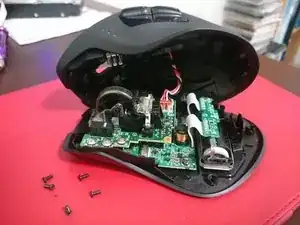
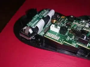
Das obere und untere Gehäuseteil sollten sich ziemlich leicht trennen lassen. Wenn nicht, dann setze einen Spudger, deinen Fingernagel oder ein Plektrum in die Naht dazwischen ein und trenne die Teile voneinander.
-
Wenn das Oberteil frei ist, dann ziehe nicht zu sehr daran, es gibt noch ein Kabel, welches die Seitentasten mit der Platine verbindet.
-
-
-
Es kann etwas knifflig sein, das Verbindungskabel zu den Seitentasten abzutrennen. Oft sitzt der Stecker im Anschluss fest, wackle dann daran, bis er allmählich herauskommt.
-
-
-
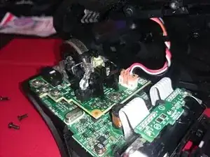
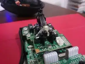
Warnung: Sei bei diesem Schritt besonders vorsichtig. Es gibt zwei winzige Federn am Mausrad. Drehe das Mausrad nicht um, wenn der Sicherungsstift entfernt ist, du verlierst sonst die Federn.
-
Stelle den Aktivierungshebel für den Freilauf wie im ersten Bild gezeigt nach oben.
-
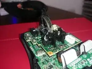
Merke dir die Stellung des Sicherungsstifts, mit dem gebogenen Teil nach unten und schiebe ihn aus dem Sockel heraus, wie im zweiten Bild gezeigt.
-
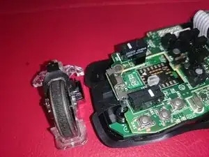
Nun solltest du das Mausrad aus seiner Halterung herausheben können. Achte auf die Federn, im dritten Bild zu sehen.
-
Diese Federn sorgen dafür, dass das Mausrad elastisch ist. Verliere sie nicht, sie sind kaum noch aufzufinden, wenn sie herausfallen.
-
Bewahre die Federn und den Sicherungsstift gut auf.
-
-
-
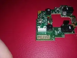
Entferne die vier Schrauben von der oberen Platine. Zwei Schrauben sind Nähe bei den Federn, zwei weitere befestigen die Mausrad-Einheit an der oberen Platine.
-
Im zweiten Bild sind die Federn zu sehen. Verliere sie nicht.
-
-
-
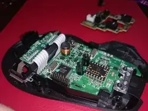
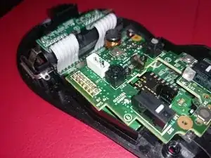
Nun muss die Verbindung zwischen oberer und unterer Platine entlötet werden. Du kannst Entlötlitze oder eine Entlötpumpe verwenden.
-
Arbeite vorsichtig und beschädige nicht das Verbindungskabel zum oberen Gehäuseteil (Bild 1, weißes Kabel). Auf dem Foto ist dies leider passiert.
-
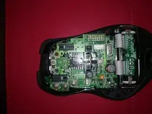
Wenn das Lötzinn komplett entfernt ist, sollte sich die obere Platine leicht abheben lassen.
-
-
-
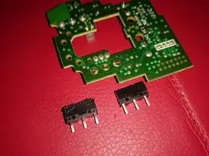
Drehe die Platine um und entlöte dem Mikroschalter. (Merke dir die genaue Position des Schalters).
-
Beseitige uberschüssiges Lötzinn von den Lötstellen des Mikroschalters.
-
Setze den neuen Schalter genauso wie den alten ein, der weiße Auslöser muss in die gleiche Richtung zeigen.
-
Wenn der Schalter beim Entlöten leichte Brandspuren erhält, ist das nicht so schlimm, er ist sowieso kaputt. Achte aber darauf, dass keine umliegenden Teile auf der Platine beschädigt werden.
-
-
-
Befestige und verlöte die Platine wieder. Schließe die Maus am Computer an und überprüfe, ob alles funktioniert.
-
Wenn alles fertig ist und gut funktioniert, hast du wieder eine einsatzfähige Maus.
-

Um dein Gerät wieder zusammenzubauen, folge der Anleitung in umgekehrter Reihenfolge.

8 Kommentare
Das Ablöten des Anschlusses ist relativ aufwändig. Mir sind dabei die Pads kaputtgegangen -> Maus ist jetzt für den Müll
I really recommend NOT doing this.
It is easier and safer to pop the switch cover and replace the metal leaf spring, and that is hard to do , but still easier than desoldering the connection bridge.
gpk -
Yeah this is not for the feint of heart. Everything went smoothly for me the first go around, but had to desolder everything I just did because I mounted the Left Click Switch the wrong way and it wasn’t making contact to click at all. Desoldering the connection bridge for the upper PCB to lower PCB is definitely much harder than it seems and having to do it twice in a row basically killed the solder joints on my upper PCB so ended up having to order a complete new one. Learn from my mistake and triple check the switches and how they go on before you desolder the old ones. The connection bridge really cannot handle too much soldering and desoldering over and over. On a plus side it seems the new PCB coming from Hong Kong has a push connector now on the underside connecting the upper and lower PCBs so no need to solder and desolder anymore if switches need to be replaced. Also, the new PCB is already upgraded to 20M switches form the original 10M.
Raisoko -