Einleitung

Der Austausch des oberen Gehäuses erfordert den Ausbau von fast allen Komponenten in deinem MacBook.

  1. RdKslWbbyVKNdorc
    • Löse die acht 4 mm Kreuzschlitz Schrauben, die die untere Abdeckung befestigen.

    According to this page http://support.apple.com/kb/HT1651?viewl..., the 8 screws are not identical.

    Can anybody tell me where each kind of screw is supposed to go?

    Gregoire -

    They are all 100% Identical. You were probably looking at a different model, or Apple has entered the wrong information... Hey, It happens...

    Owen Davies -

    The screws on the Late 2009 are identical. The blue lock compound might make tightening some require a little more effort.

    svenaustx -

    Can I replace it with a SATA 3 cable?

    nm -

    A1342 macbook does not have the right controller to support sata III

    Owen Davies -

    hi, i just got back from the apple store and they are really keen for me to upgrade to a new laptop since my battery is old and the screen is cracked, so glad i found ifixit i would love to upgrade this puppy! gonna make it a real sleeper! styler hall wrote about sticking 16 gb of ram in his a 1342 ? is this a simply mather of ordering 3 4gb sticks ?aslo i currently have 4 gb and would like to upgrade to 8 ( or indeed 16) does that mean i need to buy all new sticks or can i continue to use the old one and stick a new one next to it ?

    thanks again mick van aar, perth western aus.

    michelvanaar -

    The A1342 will take up to 16 GB of RAM, however, there are only two RAM slots, so use two 8-GB RAM modules. Other World Computing (OWC) is a great reference source for info on exactly which RAM to use with which model; prices are usually much better on EBay though. Add an SSD from OWC and your machine will really scream!

    I hope that helps!

    gdesbrisay -

    Gregoire is right. The 8 screws are absolutely NOT identical, I’m looking at them right now, weeowey weeowey.

    John Guzman -

    I just wanted to say that, in 2020, i used these instructions to replace the magsafe socket on my A1286, mid-2012, pre-Retina MacBook Pro. The internal layout is not quite the same but close enough for me to do the job. I skipped the steps of fully disconnecting the fans and speakers because of what others had said about breaking the sockets. it just meant I had to be extremely careful when lifting up the main board so that I did not tear and break the connections. I was able to disconnect the old magsafe socket with the board flat and in situ, but there was no where near enough room to be able to aline and press home the new par home. Reluctantly i had to lever up the board. This was difficult as there is a tapped post that holds a screw in the way close to where the USB sockets are, that prevented the board lifting up and out. I had to be quite forceful to manouevre the sockets out from the edge of the case.

    Paul Burridge -

    Gregoire的话确实没有问题,这八个小螺丝是五长三短,不是完全一致的

    米酒喵qwq -

  2. 1hgTLEYwbMJScnWp
    1hgTLEYwbMJScnWp
    4FfgMS2wrQ1vpKT1
    GVdOUDCoEApQ1keZ
    • Die untere Abdeckung besteht aus gummibeschichtetem Aluminium. Vermeide starkes Verbiegen der Abdeckung, da jede dauerhafte Verformung dazu führt, dass die Abdeckung nicht mehr exakt auf das Gehäuse passt.

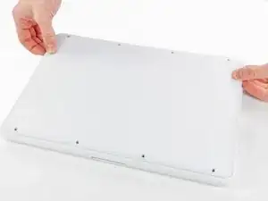
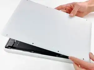
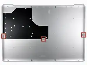
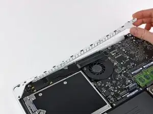
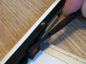
    • Hebe die untere Abdeckung vorsichtig in der Nähe der Lüftungsöffnung an.

    • Öffne den Spalt weiter mit den Fingern, bis sich die Abdeckung von den verbleibenden Clips löst.

    • Das dritte Bild zeigt die Lage der drei Clips.

    Do the retaining clips have to be re-engaged when replacing the lower case?

    John Morley -

    Answering my own question, the clips re-engage when the lower case is correctly positioned. You can help them by gently pressing the lower case with your thumbs midway along the two short sides. When everything is correctly aligned the eight screw holes line up.

    John Morley -

    Rather than running your fingernail down the sides to free up the retaining clips, I found that using an old credit card, inserted about 1/4”, to run along the left and right side popped those end retaining clips right off with no problem. You may need to twist the card slightly when in the middle area to help pop those off.

    bdahl385 -

  3. uRyXhccipZHxG6cV
    • Aus Gründen der Vorsicht empfehlen wir, den Akkuanschluss vom Logic Board zu lösen, um eine jegliche elektrische Entladungen zu vermeiden. Dieser Schritt ist optional und nicht zwingend notwendig.

    • Hebe den Akkuanschluss mit dem flachen Ende des Spudgers aus seinem Sockel auf dem Logic Board.

    • Vielleicht ist es einfacher mit den Fingernägeln auf beiden Seiten des Steckers hoch zu drücken.

    you do not need to remove the battery when replacing the hard drive or ram

    brilldoctor -

    beware not to lift the connector to close of the angle, as the picture suggest it. It might broke the angle. Attack by the middle.

    naamol -

    Not necessary?

    hikkymemo -

    Be careful of the corner of the battery cable connector when trying to pry it off with the spudge. I knocked the corner of mine. No operational impact but was not very pleasing!

    jljordanweb -

    Not necessary, but a good idea, so as to avoid any spurious charges going through the boards...

    svenaustx -

    @Svenaustx - What could happen if not removing this battery? Worst case? Not a geek on this but did change RAM on my Macbook Pro "15. Can't remember disconneting the battery back then. Shouldn't it be sufficient shutting the Mac off and ensure it has been used for an hour or so before replacing RAM?

    Allan Clarke -

    i used a metal pry and noticed some sparking when i disconnected the battery. replaced ram. now it wont turn on. did i fry it?

    Ian Lynch -

  4. QEq5LPE5LPF1bCb3
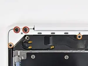
    • Entferne die folgenden Schrauben auf der Seite mit dem optischen Laufwerk am hinteren Lüftungsgitter:

    • Zwei 10 mm Torx T8 Schrauben

    • Zwei 5,2 mm Kreuzschlitzschrauben

    Hi, i have an issue with the screw in the middle: it is blocked and the top is now damaged... Any suggestion?

    Corrado -

    I have a problem with the two middle screws

    Harlan Shannon -

    same here...

    rekidjinwoo -

  5. BfDr4UQCZRL3EXi5
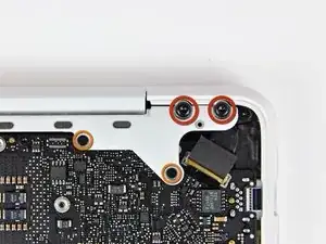
    • Entferne folgende Schrauben von der Seite mit den Anschlüssen am hinteren Lüftungsgitter:

    • Zwei 10 mm Torx T8 Schrauben

    • Zwei 5,2 mm Kreuzschlitzschrauben

    The left-most philips screw in this picture does not seem to go in properly. The best I could do was use the screw with least of the blue screwlock on it and then err on the side of leaving the white plastic a bit Ioose in that location.

    QuincyMB -

    Be very careful when putting the Torx screws back as they are very easy to leverage and seems to bend the white piece at some point, making me nervous they could crack it. Don't overdo these.

    QuincyMB -

  6. WQrdxcAe2NRocHZa
    • Hebe vorsichtig das hintere Lüftungsgitter aus dem oberen Gehäuse.

    you can actually stop disassembling now and try to replace it now. after removing two t6 screws it came off pretty easily

    grze -

    Good tip, thanks! I skipped ahead to step 17 and had no problem getting the magsafe board out from under the logic board and the new one installed. Saves a lot of work disconnecting connectors indicated as Fragile!

    matt15 -

    Thank You! Saved me an hour or so of work and a lot of stress!

    15sweyandt -

    I also did Step 6, then skipped to Step 17 & 18. Once I had the display data cable off, I could remove the 2 T6 Torx screws holding the MagSafe board on and remove it. You can reach under the logic board with the point of the spudger to work the cable out of the socket. Note how you maneuver the board out of the tight space so you can maneuver it back in. When you put the new MagSafe board in, plug in the cable first. If you bend the wires so the plug approaches the socket at the appropriate angle, you can nudge it in with the pointed end of the spudger.

    hpendleton -

    Thanks a lot for this hint! You saved my macbook, when I failed to unscrew the fan because of one completely destroyed screw. Thanks to your comment I skipped steps 7-16 and went straight to replacing the magsafe board without problems. The spudger and some 3D imagination and done,

    Sebastian M -

  7. lD6TmHB4vnYmtMC2
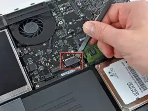
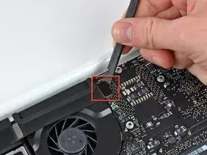
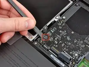
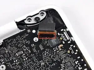
    • Benutze das flache Ende eines Spudgers, um das AirPort / Bluetooth-Flachbandkabel vom Logic Board abzulösen.

    The steps from 7 up to 16, and then 19 and 20 are not necessary. It looks like Apple intentionally designed the shape in the corner around the magsafe connector, so that it can be replaced without disconnecting and unmounting the main board. Also, the placement of the two screws mounting the magsafe board confirms that - they are easily available. This is true at least for the 2009 model, which I've successfully repaired.

    So you can skip the risky steps of disconnecting of all the main board connectors and go straight to unscrewing the magsafe connector. Then, having the spudger and some 3D imagination, you can remove the magsafe board with some 3D rotations. Same for mounting the new magsafe.

    I've found out that crucial simplification only because I failed to unscrew the fan (broken a screw completely, while following this guide step by step). Then I found a comment from user grze under step 6, which saved my macbook by confirming, that 7 to 16 can be skipped.

    Sebastian M -

  8. AEKCf4R3cOrBcDIA
    AEKCf4R3cOrBcDIA
    3kHQmPw5hSIDgfDI
    VvJNpKcwCo1nIXXE
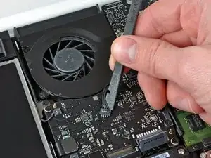
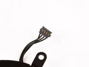
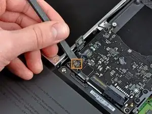
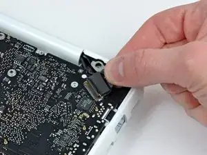
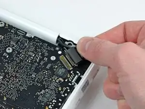
    • Heble den Lüfterstecker mit einem Spudger gerade nach oben ab und aus seinem Anschluss auf dem Logic Board heraus.

    • Es kann hilfreich sein, den Spudger dabei unter dem Lüfterkabel um seine eigene Achse zu drehen, um den Stecker zu lösen.

    • Der Lüfteranschluss und der Stecker sind auf dem 2. und 3. Bild zu sehen. Achte darauf, dass der Kunststoffanschluss des Lüfters nicht vom Logic Board abbricht, wenn du den Stecker mit dem Spudger gerade nach oben aus dem Anschluss hebst. Der Aufbau des Logic Boards (2. Bild) sieht bei dir vielleicht etwas anders aus, aber der Anschluss ist gleich.

    Since this kind of connector and very fragile and easy to damage even with a spudger I use a needle that I insert in the front side of the connector, between the connector and the socket and only apply a little pressure while lifting up the needle. The connector will then pop up from one side. Repeat the procedure for the other side. With this method it's impossible to damage the connector. I adopted this method after ruining two or three connectors using the spudger.

    lemerise -

    Hi, how do you fix the axial which connects the fan with logic board..it's broken! Thanks in advance..

    Gagandeep -

    HELP! Both the connector AND socket detached from the logic board! Is it possible (barring micro-surgery) to reattach the socket to the logic board?

    John Watson -

    same problem here...any ideas? Did you fix it again, John?

    Ben Kn -

    I disconnected the connector and socket from the logic board because I wasn't being careful and wasn't using a spudger tool as was recommended. Luckily, a friend of mine that's handy with a soldering gun was able to individually solder each wire from the cooling fan's wire assembly back onto the soldering points on the logic board. It's really intricate, tricky, and risky...but at that point, what choice do you have? I verify it's possible to fix and my cooling fan is now running perfectly fine.

    Dan Barnhart -

    Hi my name is Lynn I made a mistake on the logic board trying to detach fan from laptop

    A1342 and the whole thing came off so I was wondering do

    I solder it back on or how can I fix it thank you and be Blessed

    lynn6202388 -

  9. aRbdWBWMUbDyyAl6
    aRbdWBWMUbDyyAl6
    GrDNbMoYZMHjA1dA
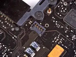
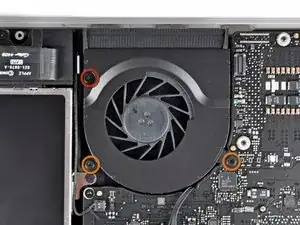
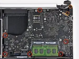
    • Entferne die folgenden drei Schrauben, mit denen der Lüfter am oberen Gehäuse befestigt ist:

    • Eine 7,1 mm Kreuzschlitzschraube

    • Zwei 5 mm Kreuzschlitzschraube

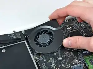
    • Hebe den Lüfter aus dem oberen Gehäuse.

  10. xxTF36FcFosA4ByK
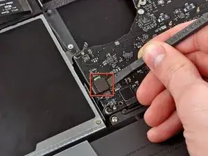
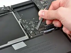
    • Löse den empfindlichen Stecker des rückwärtigen Lautsprechers vom Logic Board ab. Diese kleinen Stecker des rechten und linken Lautsprechers gehen leicht kaputt.

    • Sei sehr vorsichtig, dieser Stecker geht leicht kaputt!

    While these connectors are very delicate, a new upper body case will have new connectors already installed. I slightly broke two connectors while removing them.

    Also, the connectors have a notch underneath (on the logic board) for the corner of the spudger to fit into. The hard part is that you cannot see the notches until the connectors are removed.

    Nations81 -

    Hi. Long time ago, I know but.... How did you fix them?

    I snapped mine off, can it be soldered back on?

    Simon G -

    I used pointed tip of one side of the tweezers from the ifixit Home Tech Toolkit. I found this thinner pointed tip better than a spudger for hitting that notch in the socket underneath the connectors. Since this is a metal tool, I pried very gently and I was working on a MacBook with the battery taken out entirely (early on as suggested in the video) and was also using an Anti-Static wrist strap. I found the spudger broke one of the connectors because it's relatively thick plastic, and put too much pressure under the cables before the tip could reach the plastic block of the connector. The pressure under the cable popped the wire contact right through the top of the plastic block connector. (it was OK this connector broke since I didn't need to reuse it--my replacement keyboard/upper case came with its own cables.)

    Because the tips of the tweezers are angled, I felt I had better control of the torque I was applying than if I used a jeweler's flathead screwdriver.

    kenhtanaka -

    i used a very sharp dental pick - a tool i've permanently "added" to my ifixit tool kit bag

    pprod -

    Using a needle/pin works well. I did what another person mentioned in Step 8. Pry up from the back corner with the tip of the needle. Be gentle. One side will pop up a tiny bit. Move to the other side and gently pry there. Mine popped out completely at that point.

    stanos1 -

    Totally agree with the needle solution prying up from the side of the connector. A dentist tool is perfect!

    (yes, in 2021 i’m fixing a 2009 macbook! :P)

    Filippo Giadrossi -

  11. lO1wJVfH2ctku26v
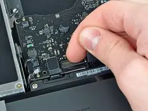
    • Benutze das flache Ende eines Spudgers, um den Stecker des optischen Laufwerks vom Logic Board abzulösen.

  12. OgAZYrc1y1DVVTTU
    OgAZYrc1y1DVVTTU
    2rPtMYrcYd1DVUnX
    • Benutze ein Spudger, um den Stecker des rechten Lautsprechers und den LED-Stecker für den Sleep-Modus vom Logic Board abzulösen.

    • Diese Stecker sind sehr empfindlich und können sehr leicht kaputt gehen.

    I broke a speaker connector on this step. I found it easier to use a tiny flathead screwdriver to gently pry these connectors up.

    brad -

    Did u manage to fix the broken speaker connexion Brad? Mine snapped off. How can I fix that?

    Simon G -

    what is the connector in the image that is two prong and has the orange and red box around it in the 3rd image? Need to replace that connector. Please help. Part number would be great

    ajfrasca -

  13. 2WKbD4n2LhqNl6Mo
    • Benutze das flache Ende eines Spudgers, um den Trackpad-Kabelstecker vom Logic Board abzulösen.

  14. 5Zq3XwyBF1DLt4r5
    5Zq3XwyBF1DLt4r5
    ndJWCwLfTHXwQSJP
    • Klappe den Sicherungsbügel am ZIF-Anschluss des Tastatur-Flachbandkabels mit dem Fingernagel hoch.

    • Schiebe das Tastatur-Flachbandkabel mit der Spudgerspitze aus seinem Anschluss.

    I had to remove the battery again to insert the keyboard ribbon cable. I just couldn't get the right angle and force otherwise.

    asciimo -

    When reassembling make sure this cable is really deep in it's socket. (Use some force with the spudger wedging it in between the cable and battery). If you don't, you won't be able to power up the board. I had 2 logicboards that I thought were dead, but it turned out the cable was not inserted enough. Jump starting them with the jump pads did nothing (with or without cable connected), but connecting the cable properly made the board come alive. Really check this!!

    Peterdk -

    You sir, just saved my day! Switching boards between two mac and I thought I broke the two at once... This should be documented on the manual!!

    jorgecarleitao -

    Thanks for your help!!! I thought I did the replacement wrong. Greetings from Peru.

    Lalo Gonzalez -

    This was hugely helpful! The cable requires much more force than expected.

    Daniel DeGrasse -

    There really should be a comment in the steps regarding tips on how to put the ribbon back in. The tape did the trick and I am back up and running.

    alexhgreene -

    The two silver squares above the left corner of the Keyboard and to the right of the Trackpad cable ribbon are the jump pads to power on the MacBook if your power button may not be working.

    Jason Ognosky -

    Accidentally I broke this flap thing. Can I replace it some point?

    Thank you!

    MJS Nope -

    Nope big job to replace it. Use Kapton tape to hold it in place. https://www.amazon.com/Retermit-Resistan...

    mayer -

  15. EceXWL1PJla3BOIe
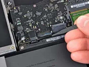
    • Benutze das flache Ende eines Spudgers, um den Stecker des Festplattenkabels vom Logic Board zu hebeln.

  16. lxuJAstsY2QBRVxy
    lxuJAstsY2QBRVxy
    nwpRGEjRp4QgvfsX
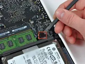
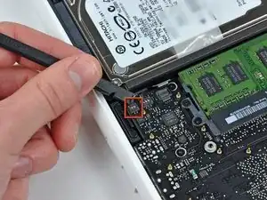
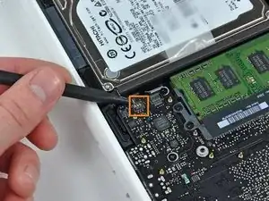
    • Benutze einen Spudger, um den linken Lautsprecherstecker und den Mikrofonstecker vom Logic Board zu hebeln.

    • Diese Stecker sind sehr empfindlich und gehen leicht kaputt.

    Note: the 2009 and 2010 model differ here. On one the 3 point connector is left and 2 point is right, on the other one the 3 point connector is right and 2 point is left.

    I found this while installing several logicboards for A1342.

    Peterdk -

    @Peterdk, are the connectors exchangeable?

    I mean, would putting the 3 pin on the 3 pin, and the 2 pin on the 2 pin, regardless of the position (left or right) be ok?

    Have you successfully used a 2010 logic board on a 2009 case?

    Alberto Einstein -

    I can't seem to connect those any suggestions

    Ayat -

    how do you reconnect these?

    yourstruly69101 -

    hi! i know iʻm 6 years late, and you probably figured it out already, but for the rest of us newbies , line the plug over the socket and gently press down. the correct orientation of the plug is the side with the tiny slots in them faces the logic board, aligning with the contacts in the socket. it may help to press the side farthest from the ribbon cable first.

    Kahana -

  17. iOPLflAfChGFt2eI
    iOPLflAfChGFt2eI
    iVjdrIVZ1hALQLUE
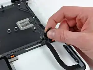
    • Fasse die Zuglasche aus Kunststoff, die an der Kabelverriegelung des Displays befestigt ist, und drehe sie in Richtung der DC-In-Seite des Computers.

    Just lift the tab up slightly to release the clip that secures the data display cable. Then the cable will slide out easily.

    matt15 -

    If the video data cable has been disconnected before, the adhesive on the might not hold. Be extra cautious in disconnecting this. An illuminated magnifier would be a good help on this step as it is very delicate. This was where I feared I would fail. Was very relieved in getting through this step...

    svenaustx -

    I wasn't careful enough here, and didn't realize that the silver metal piece around the connector is actually a locking clip. No wonder disconnecting the cable required more than a gentle pull. The clip popped out of the cable-side connector in the process, and was bent; fortunately I was able to very carefully bend the clip out just enough to get it re-seated in the connector; there are tiny slots on the sides of the connector that the clip fits into.

    kmcrawford111 -

  18. KyyPPYagxuvikG5o
    KyyPPYagxuvikG5o
    NZjNxru4jxkRtcp1
    • Ziehe den Stecker des Display-Datenkabels vorsichtig aus seinem Anschluss auf dem Logic Board heraus.

    • Ziehe den Anschluss parallel zur Oberfläche des Logic Boards.

    • Der Anschluss des Display-Datenkabels ist aus sehr dünnem Metall und verbiegt sich leicht. Achte darauf, dass du den Stecker gerade aus dem Anschluss ziehst.

  19. pYlV2OctFNVf1UUn
    • Entferne die sechs 4,1 bis 4,4 mm T6 Torx Schrauben, mit denen das Logic Board am Obergehäuse befestigt ist.

    • Entferne die beiden 4,1 bis 4,5 mm T6 Torx Schrauben, mit denen die MagSafe-Platine am Obergehäuse befestigt ist.

    • Bei einigen Modellen können dies Schrauben der Größe T7 sein. Achte darauf, dass du den Kopf nicht mit einem kleineren Bit beschädigst.

    incorrect photo of motherboard...

    Devin R -

  20. DwBEKTfNSKlvjFPB
    DwBEKTfNSKlvjFPB
    2fMtbh2evvZrnxJa
    FNTVebXtTjhWRsxy
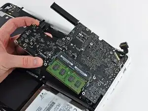
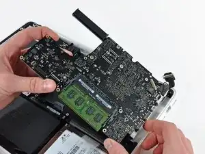
    • Hebe die Seite des Logic Boards, die den Anschlüssen gegenüberliegt, aus dem oberen Gehäuse heraus.

    • Drehe das Logic Board vom oberen Gehäuse weg, bis die Anschlüsse den Rand des oberen Gehäuses freigeben.

    • Ziehe das Logic Board und die MagSafe-Platine in einem Stück von der Kante des oberen Gehäuses weg.

    • Die MagSafe-Platine kann bei diesem Vorgang versehentlich abgetrennt werden. Vergewissere dich vorsichtshalber, dass der Stecker der MagSafe-Platine fest in seinem Anschluss sitzt, bevor du das Logic Board wieder in das obere Gehäuse einsetzt.

    • Bevor du das Logic Board wieder in das obere Gehäuse schiebst, vergewissere dich, dass die Kabel des linken Lautsprechers und des Mikrofons in den dafür vorgesehenen Kanälen im oberen Gehäuse liegen (siehe drittes Bild).

    (When re-installing) Before screwing down the logic board, go around the edge and make sure no cables are caught underneath, remember there are 11 of them, 12 if the battery is present at this point.

    kenhtanaka -

    I reassembled the macbook A1342 using this guide and everything is perfect, except that if I shut down the computer and power it up after 1hour or so, I have to press the power button a few times before it starts. What could I have gone wrong? I checked the magsafe connector and it seems to be firmly seated. :(

    Alok -

  21. KPiif3fTbAkCRCQ2
    KPiif3fTbAkCRCQ2
    uLRRfALdNRcvLvtV
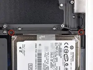
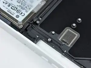
    • Entferne die beiden Kreuzschlitzschrauben, mit denen die Festplattenhalterung am oberen Gehäuse befestigt ist.

    • Es handelt sich hierbei um unverlierbare Schrauben, d.h. sie bleiben der Festplattenhalterung hängen.

    • Entferne die Festplattenhalterung vom oberen Gehäuse.

  22. Wy5xfAxFJ1UFTLjI
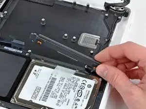
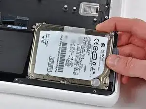
    • Hebe die lose Seite der Festplatte an und ziehe sie von der Seite des oberen Gehäuses weg.

    • Die Festplatte ist noch über das Festplattenkabel mit dem oberen Gehäuse verbunden.

  23. LtETQyKZI34J1Sdh
    LtETQyKZI34J1Sdh
    YS4OOfVxtA6H1DqA
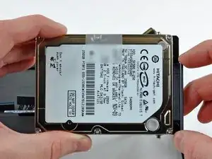
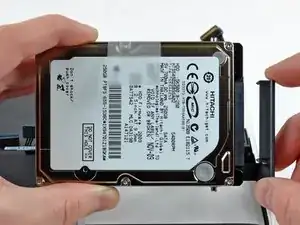
    • Trenne die Festplatte ab, indem du den Festplatten-Kabelstecker aus seinem Anschluss auf der Festplatte ziehst.

  24. qhDanC5VEgDdYAWJ
    qhDanC5VEgDdYAWJ
    4pu6JRgEsKGgP2ox
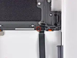
    • Entferne die einzelne 3,1 mm Kreuzschlitzschraube, mit der das Festplattenkabel am oberen Gehäuse befestigt ist.

    • Hebe das Festplattenkabel aus dem oberen Gehäuse.

  25. XmZpFBMcwJHB46Bf
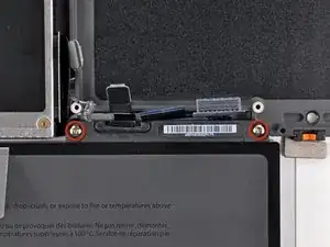
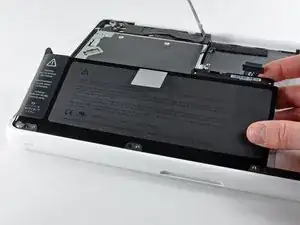
    • Entferne die beiden 5 mm Tri-Wing-Schrauben, mit denen der Akku nahe beim Akkustecker am oberen Gehäuse befestigt ist.

  26. HpZnHWUepg6MBC2J
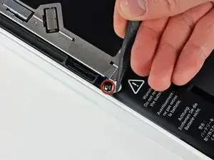
    • Löse die Ausbuchtung des Warnaufklebers vorsichtig mit der Spudgerspitze ab, um eine versteckte Tri-Wing-Schraube freizulegen.

    • Entferne die 5 mm Tri-Wing-Schraube, mit der der Akku am oberen Gehäuse befestigt ist.

  27. sZDg6XBad4DTCAQI
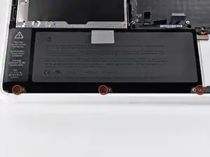
    • Entferne die drei 3,1 mm Kreuzschlitzschrauben, mit denen der Akku nahe an der Kante des oberen Gehäuses befestigt ist.

    • Stelle beim Wiedereinbau des Akku sicher, dass diese drei Schrauben eingebaut sind, bevor du die Tri-Wing-Schrauben einsetzt. Achte auf das Tastatur-Flachbandkabel, unter Umständen musst du das Flachbandkabel mit dem flachen Ende des Spudgers weghalten, während der Akku wieder an seinen Platz heruntergeklappt wird.

    When reinstalling, I leave this step till last. It'll help you get that frackin keyboard ribbon inserted.

    maccentric -

  28. 3iaFBSFYwZOCSX4Z
    • Hebe den Akku nahe an seinem Stecker an und entferne ihn aus dem oberen Gehäuse.

    • Wenn du den Akku ersetzt, achte darauf, dass das Tastatur-Flachbandkabel nicht darunter eingeklemmt wird.

  29. Z4UFnRnw2XOMjLOs
    Z4UFnRnw2XOMjLOs
    NfKartejPI4HJuYM
    ATsvL6d6HaSgWnE3
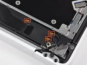
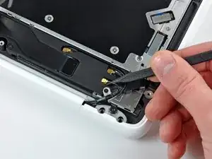
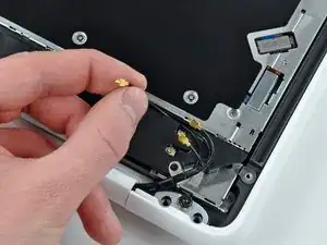
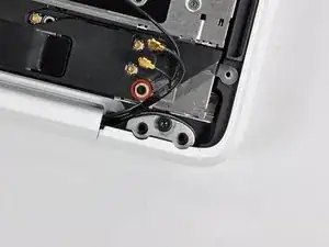
    • Heble die AirPort/Bluetooth-Stecker (insgesamt drei) mit der Spudgerspitze von der Airport-/Bluetooth-Platine ab.

    • Hole, wenn nötig, das lange Antennenkabel aus seinem Schlitz im Gehäuse des rückwärtigen Lautsprechers heraus.

    To save some time and frustration, leave the antennae connected, just take off the 3 screws holding the speaker down and lift it out of the way. You will remove everything with the screen.

    maccentric -

  30. Kr253phrhGb1mH5M
    • Entferne die einzelne 3 mm Kreuzschlitzschraube, mit der die Antennen-Erdungsstreifen am Gehäuse des rückwärtigen Lautsprechers befestigt sind.

  31. qDu33bRIwbrQwOhl
    • Entferne die einzelne 2,2 mm Kreuzschlitzschraube, die waagrecht in die Seite des optischen Laufwerks eingesetzt ist.

    I couldn’t access this screw with the screwdriver I had (socket head was too big). But I didn’t need to remove this screw anyway. Just leave the speaker assembly (step 33) attached to the optical drive.

    Vaughn Berger -

  32. EFUyXuKreRUBHxde
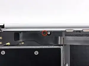
    • Entferne die einzelne 12 mm Kreuzschlitzschraube, mit der der rückwärtige Lautsprecher am oberen Gehäuse befestigt ist.

  33. Lad5KHnOBFhTvFTZ
    • Entferne den kompletten rückwärtigen Lautsprecher aus deinem MacBook.

  34. 4KMJKULE4PfpWhFv
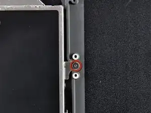
    • Entferne die einzelne 4,5 mm Kreuzschlitzschraube, mit der die innere Kante des optischen Laufwerks am oberen Gehäuse befestigt ist.

  35. HPRCnGC1eYqjwhKq
    • Entferne die beiden 2,5 mm Kreuzschlitzschrauben, mit denen das optische Laufwerk nahe an der Öffnung des optischen Laufwerks am oberen Gehäuse befestigt ist.

  36. 1LPAIKocwc1NtEOH
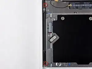
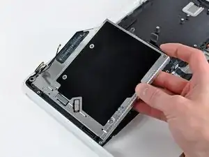
    • Hebe das optische Laufwerk nahe an seinem Stecker hoch und ziehe es vom oberen Gehäuse weg, um es aus dem Computer zu entfernen.

  37. lYwBqCEUCoeJHF52
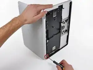
    • Öffne dein MacBook so, dass das Display in einem rechten Winkel zum oberen Gehäuse steht.

    • Stelle dein geöffnetes MacBook wie gezeigt auf einen Tisch.

    • Halte das Display und das obere Gehäuse mit der linken Hand fest, während du die noch übrige Torx T8 Schrauben von der unteren Displayhalterung entfernst.

    • Bevor du die Torx T8 Schrauben wieder festziehst, schließe das Display und justiere es so, dass die hinteren Kanten des oberen Gehäuses und des Displays miteinander ausgerichtet sind und die Abstände an den Enden der Scharniere gleich sind.

    Torx screws could be T9 and not T8. Be sure your Torx driver fits snugly into the screw so that you don't strip it.

    evandove -

  38. Uo6QUJvofyDbG1sI
    • Achte unbedingt darauf, dass du das Display und das obere Gehäuse gut mit der linken Hand festhältst, da sie sonst herunterfallen und beschädigt werden können.

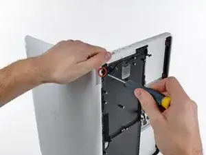
    • Entferne die letzte Torx T8 Schraube, mit der das Display am oberen Gehäuse befestigt ist.

  39. p2bWTYpHQdRPgBYE
    p2bWTYpHQdRPgBYE
    iDV1XJTZHRr5GYYO
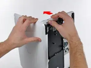
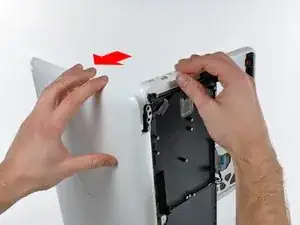
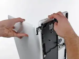
    • Fasse das obere Gehäuse mit der rechten Hand und drehe es leicht in Richtung Oberkante des Displays, sodass die obere Displayhalterung die Kante des oberen Gehäuses freigibt.

    • Durch das Displaydatenkabel kann die obere Displayhalterung am oberen Gehäuse festhängen. Es kann daher hilfreich sein, das obere Gehäuse leicht vom Display wegzudrehen, damit mehr Platz ist.

    • Drehe das Display leicht vom oberen Gehäuse weg.

  40. C4DjKmASqYLMLXVZ
    • Hebe das Display hoch und vom oberen Gehäuse weg, achte dabei darauf, dass sich keine Halterungen oder Kabel verfangen.

  41. FHf24JkjNRWaujcH
    FHf24JkjNRWaujcH
    Da6iErjkl1MyCLLW
    DDjGpUDMaxBjvuHZ
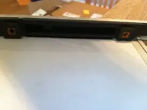
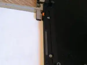
    • Die Festplatte sitzt in vier orange-schwarzen Gummieinsätzen. Eine Seite hat volle Kreise und die andere Seite hat halbe Kreise. (Die andere Seite der Halbkreise befindet sich an der Festplattenhalterung, die zuvor ausgebaut wurde).

    • Das neue obere Gehäuse hat diese Einsätze möglicherweise nicht. Achte darauf, sie aus dem alten Gehäuse auszubauen und in das neue einzusetzen.

    • Die Einsätze lassen sich leicht mit einem Spudger oder einem flachen Schraubendreher heraushebeln. Sie sind nicht eingeklebt, sondern haben eingekerbte Seiten, damit sie an der richtigen Stelle bleiben.

Abschluss

Um dein Gerät wieder zusammenzubauen, folge den Schritten dieser Anleitung in umgekehrter Reihenfolge.
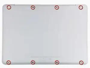
Andrew Bookholt

593241 Reputation

0 Kommentare