Einleitung

Hier findest du eine Übersicht darüber, wie du die Kühleinheit und den Prozessor des Apple G5 austauschst. Wegen der Designbeschränkungen des Geräts ist es schwierig, nur den Prozessor selbst auszutauschen, ohne dabei die ganze Einheit dauerhaft zu beschädigen. Deshalb wird in diesem Teil der Anleitung nur gezeigt, wie man die gesamte Einheit ausbaut.

  1. UaBGTOEf6dyVJEiV
    • Um einen Stromschlag zu vermeiden, schalte den Computer aus und entferne das Netzkabel. Öffne niemals den Computer oder versuche Komponenten im Inneren einzubauen, solange der Computer an ist.

    • Um Verbrennung zu vermeiden, warte mindestens 10 Minuten, um die inneren Komponenten des Computers abkühlen zu lassen.

  2. rBARHUQtVA6lfOWt
    • Entferne alle Kabel, auch das Netzkabel, bevor du den Computer öffnest.

  3. EfcrMHyp4XqEbYsn
    EfcrMHyp4XqEbYsn
    LG2YPVaHQQ1nWjIE
    • Ziehe den Hebel heraus, um die Seitenabdeckung zu entriegeln.

    • Die Seitenabdeckung sollte herausfallen. Wenn dies nicht der Fall sein sollte, ziehe ein wenig an den Kanten der Seitenabdeckung.

  4. mFQ5PLHCQCclToTc
    mFQ5PLHCQCclToTc
    GbBxDZVgNRe2CrnX
    SMxAYMZYyFRqRxWs
    • Entferne das Luftleitelement (die durchsichtige Plastikabdeckung) durch Ziehen am Griff.

  5. IDAAGqatkHs6FhEn
    • Lokalisiere die vordere Lüftereinheit.

  6. Ue42sEAaPLVThCVP
    • Ziehe die Lüftereinheit heraus; sie sollte problemlos herauskommen.

  7. APBogP6JMWqGqlmB
    APBogP6JMWqGqlmB
    IjEMgRgN1NBVvwHG
    • Auf dem Foto ist die Baugruppe rot umrandet (in einem Kasten).

  8. pIUQgt6qMGFVyqFA
    pIUQgt6qMGFVyqFA
    NRx1OuVgLXIqegCg
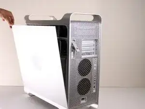
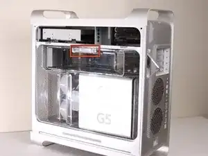
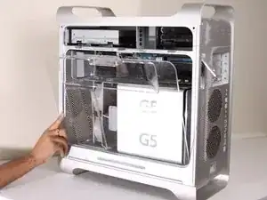
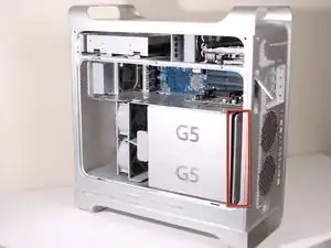
    • Entferne die G5 Metal Abdeckung vom Computer.

    • HINWEIS: Apple hat einen ziemlich zerbrechlichen Kunststoff-Stift eigesetzt, welcher von oben eigesetzt wird und in ein versteckten Teil einrastet. Wenn du diesen Stift entfernst, dann erlischt die Garantie deines PowerMac G5. Ein Ersatz-Stift zu bekommen ist sehr schwierig und nur wenige bekommen den Stift entfernt ohne diesen zu beschädigen.

    • Wenn die Garantie sowieso schon abgelaufen ist, dann kann es dir egal sein, was höchstwahrscheinlich auch schon der Fall ist.

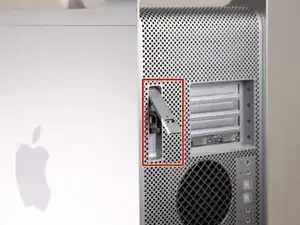
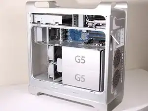
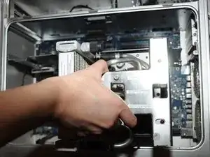
    • Ziehe die Metall-Platte nach links und entferne diese anschließend.

    The whole pin assembly acts like a miniature toggle bolt. The inner part of the pin assembly is actually a short stubby cylinder. When the pin is inserted into the sleeve, it presses on the sleeve and expands it slightly in the processor shield, locking it to the top divider shield.

    I took a tiny drill bit and spun it into the center of the pin just enough so that I could insert a small sharp screw (I used a cup hook) into the pin. All it needed was just a slight tug, and the pin came out of the outer locking sleeve. I used the same screw to remove the outer sleeve.

    Steve -

    I was able to push the bottom part of the shield to the left and unhook the bottom first. I then took a long wooden skewer (18" long) and pushed the center pin out. I then took a pair of needle nose pliers and gripped the two flared ends of the outer sleeve and squeezed them together and pushed the sleeve out of the hole. It was actually pretty easy this way and there was no damage to the pin or the sleeve.

    cuchetti -

    Take a flat head screwdriver and lift a little on the top plate on the top of the cover so as to lift the plastic part slightly. Apply pressure near the top of the plastic keeper and separate it slightly from the metal. Take a box cutter blade and apply pressure around the outside not on the center of the pin. Once you can separate the pin a little from the outside edge take a long strand of glide dental floss and rope it around the pin inside the plastic holder and pull up. Do the same to the outer keeper piece and VOILA!

    Ann Zevely -

  9. H1F6CSACH5Vl2d25
    • Die Lüfter-Baugruppe ist mit einem roten Rand umrandet.

  10. XBuUMdyGOTu1P3EL
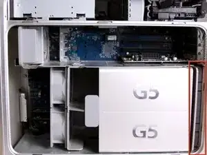
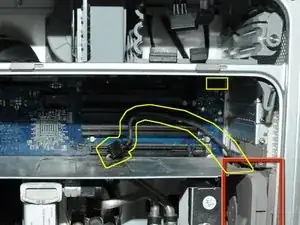
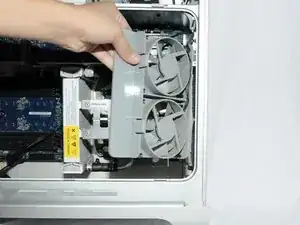
    • Trenne die Verbindung der Lüfter-Baugruppe vom LogicBoard. Wenn eine Grafikkarte eingebaut ist, dann musst du die Verbindung vorsichtig herunterziehen, zwischen der Grafikkarte und dem LogicBoard

    • Das Foto zeigt bereits die getrennte Verbindung der Lüfter-Baugruppe vom LogicBoard, keine Grafikkarte ist auf dem Bild eingebaut. Gelb eingezeichnet ist, wo das Kabel normalerweise angeschlossen ist bzw. wo es liegt.

    To disconnect the cable, it's easier to remove all the cards. I had filled up all 4 slots and I need to space to get my hand in there to disconnect the cable.

    Lawrence -

  11. ei5NFSAMeQA2oFIx
    ei5NFSAMeQA2oFIx
    iEX1ZmUvy1TP3Wfo
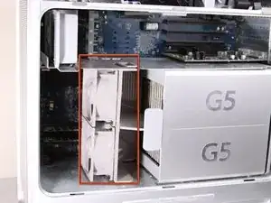
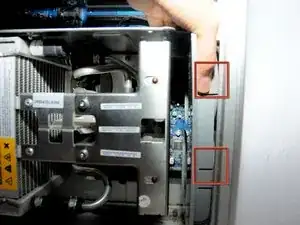
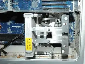
    • Die Halterung der Lüfter-Baugruppe ist Rot mit den beiden Kästen umrandet.

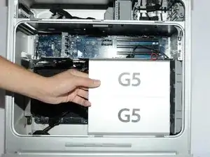
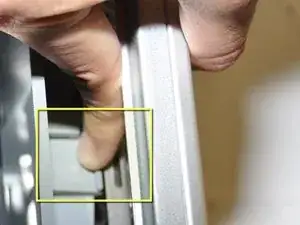
    • Während du diese runterdrückst, musst du die Lüfter zurück ziehen in Richtung Kühlung.

  12. CuTPmTvUlTPNZZJV
    CuTPmTvUlTPNZZJV
    YCQAO35kl154ToAL
    • Nach dem die Baugruppe ausgehakt ist, kannst du die Lüfter herausziehen.

    Before pulling fan, you must unplug fan power cable from upper right-most corner of mother board (connection J45). Carefully pull cable down past the video card's back-side.

    Sam Taylor -

    Thank you for this mention. It seems important, do you have a snapshot of it?

    Is it hard to find/reach?

    And plugging it back in with the new one, any problems?

    Thanks!

    Diana -

  13. rHV4aKaP4nCrfXLF
    • Nachdem die Baugruppe entfernt ist, müsste es so in etwa wie auf dem Bild aussehen.

  14. unuZQVVtxhJuG5Jk
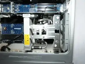
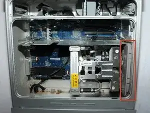
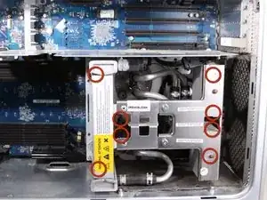
    • Die Kühleinheit des PowerMac G5 ist rot umrandet.

    • Lege das CPU-Gehäuse mit der Öffnung nach oben auf die Rückseite, dann sind die nächsten Schritte leichter.

  15. UnfZrGxywHkyWCvg
    UnfZrGxywHkyWCvg
    camHc21FU1I1mPml
    DmSHQQNRsEsJuGjG
    • Entferne die 8 rot umrandeten T10 Schrauben von der Kühlungseinheit. HINWEIS: Für diese Schrauben braucht man Inbusschlüssel.

    • Das bevorzugte Werkzeug sind Inbusschlüssel mit langem Griff. T10 hat eine Größe von 2,74 mm (der nächstpassende Inbusschlüssel hat eine Größe von 2,5 oder 3 mm) und T15 hat eine Größe von 3,27 mm (der nächstpassende Inbusschlüssel hat eine Größe von 3 mm oder 4 mm). Achte darauf, hochwertiges und geeignetes Werkzeug zu verwenden.

    • Die Schrauben sind teilweise verdeckt, du kannst diese also nicht auf dem Bild sehen

    • Wenn du 3 Arbeitsschritte weiter siehst, erkennst du die genaue Lage der Schrauben.

    • Die Schrauben kann man nur lösen und nicht entfernen. Das ist Absicht.

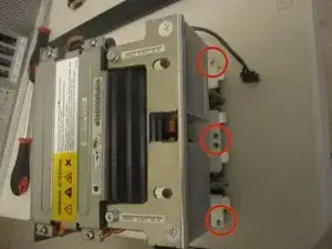
    • Auf den letzen beiden Bilder sieht man eine andere, ausgebaute Version des LCS (Liquid Cooling System - Wasserkühlung) aus einem anderen Blickwinkel, um die 8 Löcher für die Schrauben zu zeigen.

    that looks completely different and I can't unscrew it :/

    grze -

    Did you find a solution for yours? I may have the same problem.

    jaesonk -

    Very difficult on some models.

    Nate Aguilar -

  16. dIuHvGxNu5HwTWQN
    • Ziehe die Kühleinheit mit dem Prozessor gerade nach oben, um eine Beschädigung der Hauptplatine zu vermeiden.

    • Das ist nicht ganz einfach und sollte mit Vorsicht erfolgen, um Beschädigungen zu vermeiden.

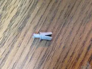
    • Die Hülsen um die 6 Schrauben halten das Teil möglicherweise fest. Nimm in diesem Fall eine Spitzzange und drücke die Hülsen vorsichtig zusammen, bis es sich löst.

    • Ziehe zuerst den Boden und dann die Seite in Richtung des unteren Teils des CPU-Gehäuses, um die untere Kühlmittelmanschette um die Kühlkörperhalterung herum zu verschieben. *Kühlkörperhalterung nicht abgebildet*

  17. m5AnLOVWUlwpwGFJ
    • Ziehe das Kabel ab.

  18. JqoU2Yt3FYiiXQSQ
    • HINWEIS: Hier sind die Abstandshalter ohne installierte Kühleinheit abgebildet, damit du besser erkennen kannst, wo sich die Schrauben befinden. Entferne die unteren zwei Abstandshalter, damit du das Netzteil leichter herausnehmen kannst.

    • Überprüfe die Pin-Verbindungen auf Beschädigungen. Alle gelb markierten Pins müssen gerade stehen und dürfen nicht verbogen sein. BERÜHRE DIE PINS NICHT. Ein verbogener Pin führt dazu, dass sich dein Computer nicht einschalten lässt.

Abschluss

Um das Gerät wieder zusammen zu bauen, musst du die Anleitung in umgekehrter Reihenfolge befolgen.

Nolan

Mitglied seit: 14/01/10

2244 Reputation

5 Kommentare

This is a great teardown/guide! you should email one of the iFixit staff members and have them post it so the whole community can see it!

Chris Green -

I have a different cooling apparatus in my Quad Core than the one pictured here. It has a wider radiator on the left side and two black pumps on the right side. The pumps are elevated away from the CPUs. Nearest the CPUS is a grey plastic covering with Cooligy printed on it.

I can only find 6 of the 8 screws mentioned in STEP 15. The unit will not come out. If the 2 remaining screws are as pictured in STEP 18, then they would be directly under my radiator. Do I need to remove that too?

jaesonk -

Kaesong,

I have the same problem with a G5 Dual 2.5 Quad core (version 2) LCS. I am about to loose it. Did you ever find out how to get the LCS off the mother or logic board? Please let me know.

Mark

castsmooth@yahoo.com

Mark Stevens -

On the Delphi / Cooligy model the hex ball end screws behind radiator have got to come out following the crossbar there are 2 10 T that are flathead with no washer note that because they have to go back same way. Do not forget the Power Buss for processor the powerleads have to be disconnected because processor board is under them. The Delphi / Cooligy has 2 pumps and was the least successful implementation of the LCS. Panasonic later made one which was great and sold as a replacement for the Delphi / Cooligy for a replacement (THE BEST IMPLMENTATION) of the LCS. Hope this help battling on of these beast myself.....

Edward Johnson -

@Edward, you are 100% mistaken about the Panasonic and Delphi / Cooligy LCSs: it was the OTHER way around: the early 2005 liquid-cooled systems are the ones that gave the G5 a bad fame of leakage, which used Panasonic radiators, which is the reason you almost never see 2.7GHz models that still live, while the late-2005 Quad replaced that with Delphi ones (both version 1 and 2).

Both version 1 and 2 are extremely reliable, which is why so many Quads still exist today (my own included), and most existant 2.7GHz G5 owners today, who are already so few, saved their machines precisely by replacing the faulty Panasonic LCS one with a Delphi one (same one found in the Quads).

People debate which version (1 or 2) is better, too, but there’s no existent reliable report so far. But it’s speculated version 2, as the numbering suggests, is a revision for even further reliability (perhaps by evening out the cooling for each processor contained by having 2 pipes).

donots2006 -