
Einleitung
Benutze diese Anleitung, um die Frontabdeckung deines Valve Steam Deck LCD auszutauschen oder auszubauen.
Achte während der Reparatur auf allgemeine Vorsichtsmaßnahmen zur Vermeidung von elektrostatischen Entladungen (ESD = engl. electrostatic discharge).
Für diese Reparatur muss fast das komplette Gerät zerlegt werden, auch das Display muss ausgebaut werden. Du wirst Ersatzklebestreifen sowohl für das Display, als auch für die Lautsprecher benötigen.
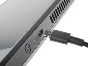
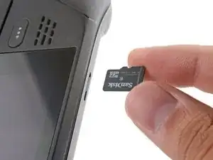
-
-
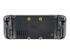
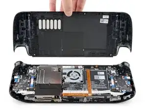
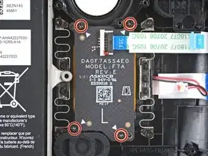
Entferne die acht Kreuzschlitzschrauben, mit denen die Rückabdeckung befestigt ist:
-
Vier 9,5 mm lange Schrauben mit Grobgewinde
-
Vier 5,8 mm lange Schrauben mit Feingewinde
-
-
-
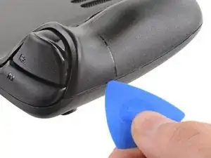
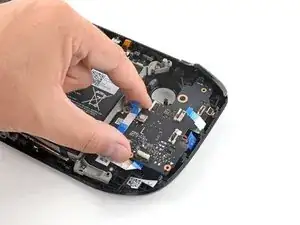
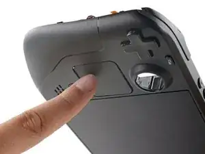
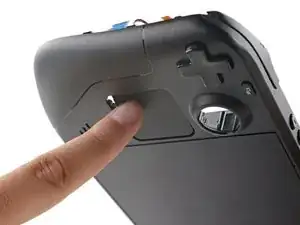
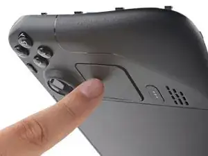
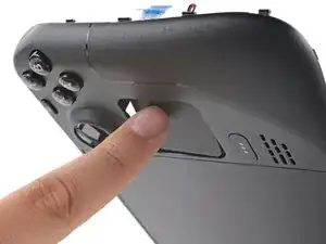
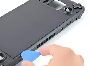
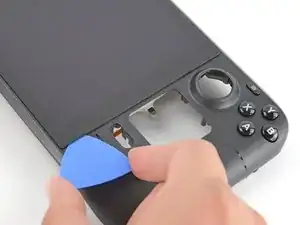
Setze ein Plektrum in die schmale Fuge zwischen Rückabdeckung und Vorderschale an der Kante des rechten Griffs ein.
-
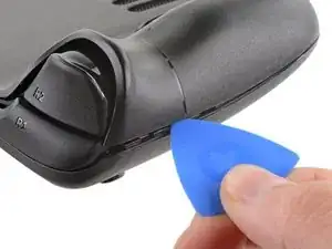
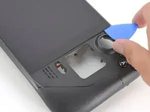
Heble die Rückabdeckung hoch, um sie aus den Clips zu lösen, mit denen sie befestigt ist.
-
-
-
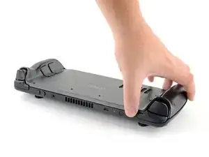
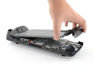
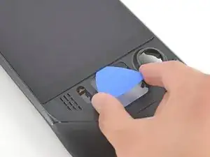
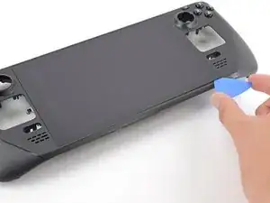
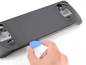
Fasse die Rückabdeckung an der Öffnung, die du gerade erstellt hast, und ziehe sie nach oben vom Gerät weg, um die Clips an den langen Kanten zu lösen.
-
Entferne die Rückabdeckung.
-
-
-
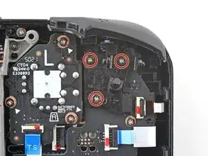
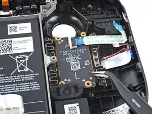
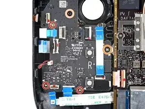
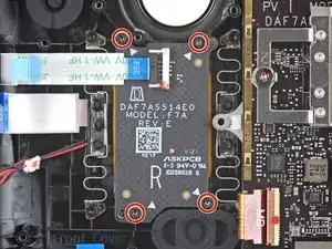
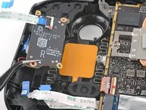
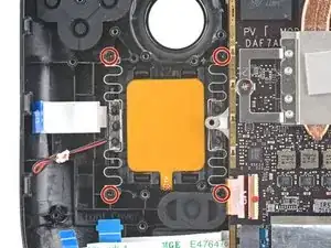
Benutze einen Schraubendreher, um die drei Kreuzschlitzschrauben zu entfernen, mit denen die Abschirmung der Platine befestigt ist:
-
Eine 3,4 mm Schraube
-
Zwei 3,7 mm Schrauben
-
-
-
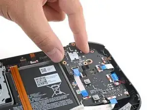
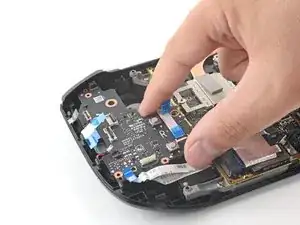
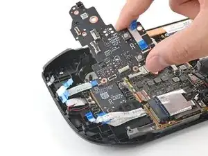
Fasse das Akkukabel an seiner Zuglasche und ziehe es vom Motherboard weg, um es abzutrennen.
-
-
-
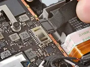
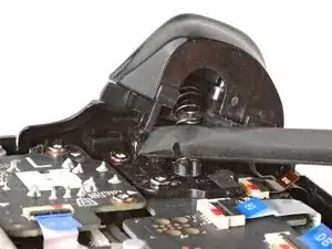
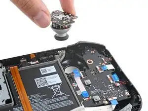
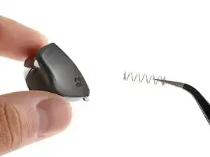
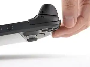
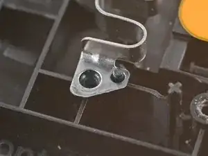
Setze das flache Ende eines Spudgers auf die Innenkante des linken Clips des Triggers.
-
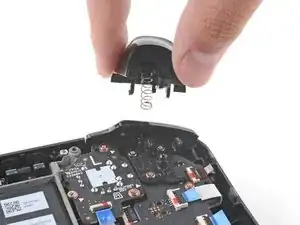
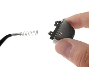
Klappe den Trigger-Clip heraus, und aus dem Stift nach oben heraus, um ihn zu lösen.
-
-
-
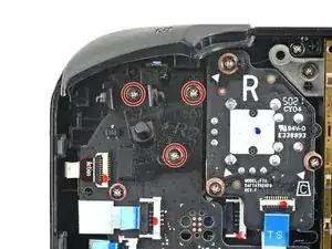
Benutze einen Kreuzschlitzschraubendreher, um die drei 5,2 mm Schrauben zu entfernen, mit denen die linke Trigger-Halterung befestigt ist.
-
-
-
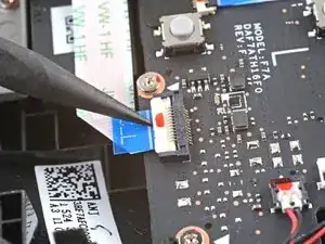
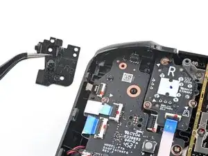
Benutze das spitze Ende eines Spudgers, um den kleinen Sicherungsbügel am ZIF-Verbinder des Analogstick-Kabels anzuheben.
-
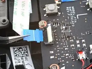
Schiebe das Kabel mithilfe einer Pinzette aus seinem Anschluss.
-
-
-
Benutze einen Kreuzschlitzschraubendreher, um die drei 5,2 mm Schrauben zu entfernen, mit denen der Analogstick befestigt ist.
-
-
-
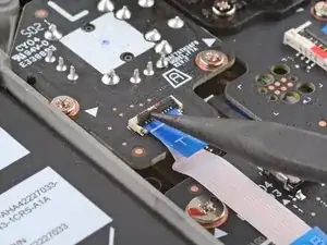
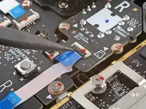
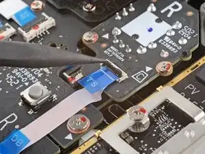
Benutze das spitze Ende eines Spudgers, um den kleinen Sicherungsbügel am ZIF-Verbinder des Verbindungskabels zur Tastenplatine hochzuheben.
-
Schiebe das Kabel mit einer Pinzette aus seinem Anschluss.
-
-
-
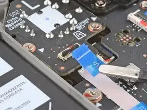
Es kann sein, dass manche Stecker mit Klebeband bedeckt sind. Entferne es mit einer Pinzette.
-
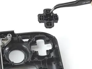
Benutze das spitze Ende eines Spudgers, um die kleinen Sicherungsbügel an den restlichen ZIF-Verbindern der Tastenplatine hochzuheben. Schiebe die Kabel mit einer Pinzette aus ihren Anschlüssen:
-
Trenne das Kabel des Steuerkreuzes (D-Pad) ab.
-
Trenne das Kabel der Touchpad-Platine ab.
-
Trenne das Touchpad-Kabel ab.
-
-
-
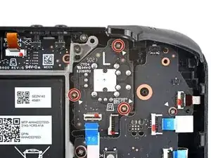
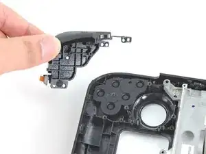
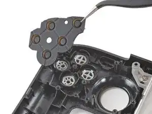
Benutze einen Kreuzschlitzschraubendreher, um die vier Schrauben zu entfernen, mit denen die linke Tastenplatine befestigt ist:
-
Drei 5,2 mm Schrauben
-
Eine 3,9 mm Schraube
-
-
-
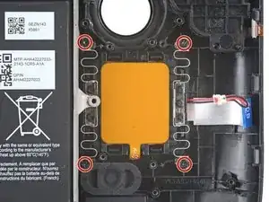
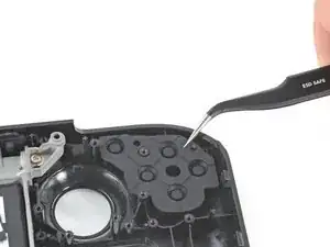
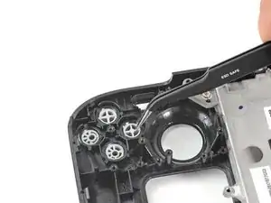
Benutze einen Kreuzschlitzschraubendreher, um die vier 4,7 mm Schrauben zu entfernen, mit denen die Touchpad-Platine befestigt ist.
-
-
-
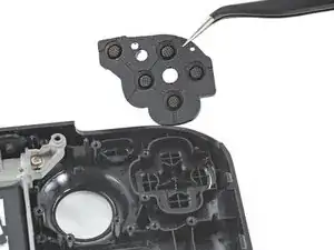
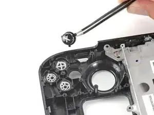
Benutze einen Kreuzschlitzschraubendreher, um die vier 4,7 mm Schrauben zu entfernen, mit denen das Touchpad befestigt ist.
-
-
-
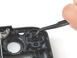
Drücke das linke Touchpad von der Vorderseite des Steam Deck her etwas durch die Vorderschale, um es abzulösen.
-
Hebe das Touchpad unter dem überhängenden Bereich des Mittelrahmens heraus.
-
Entferne das Touchpad.
-
-
-
Setze das flache Ende eines Spudgers auf die Innenkante des rechten Clips des Triggers.
-
Klappe den Trigger-Clip heraus, und aus dem Stift nach oben heraus, um ihn zu lösen.
-
-
-
Benutze einen Kreuzschlitzschraubendreher, um die drei 5,2 mm Schrauben zu entfernen, mit denen die rechte Trigger-Halterung befestigt ist.
-
-
-
Benutze das spitze Ende eines Spudgers, um den kleinen Sicherungsbügel am ZIF-Verbinder des Analogstick-Kabels anzuheben.
-
Schiebe das Kabel mithilfe einer Pinzette aus seinem Anschluss.
-
-
-
Benutze einen Kreuzschlitzschraubendreher, um die drei 5,2 mm Schrauben zu entfernen, mit denen der Analogstick befestigt ist.
-
-
-
Verwende das spitze Ende eines Spudgers, um den kleine Sicherungsbügel am ZIF-Verbinder des Tastenplatinen-Kabels anzuheben.
-
Schiebe das Kabel mit einer Pinzette aus seinem Anschluss.
-
-
-
Benutze das spitze Ende eines Spudgers, um den kleinen Sicherungsbügel am ZIF-Verbinder des Tastenplatinen-Verbindungskabels hochzuheben.
-
Schiebe das Kabel mit einer Pinzette aus seinem Anschluss.
-
-
-
Es kann sein, dass manche Stecker mit Klebeband bedeckt sind. Entferne es mit einer Pinzette.
-
Benutze das spitze Ende eines Spudgers, um die kleinen Sicherungsbügel an den restlichen ZIF-Verbindern der Tastenplatine hochzuheben. Schiebe die Kabel mit einer Pinzette aus ihren Anschlüssen:
-
Trenne das Kabel der Aktionstasten ab.
-
Trenne das Kabel der Touchpad-Platine ab.
-
Trenne das Touchpad-Kabel ab.
-
-
-
Benutze einen Kreuzschlitzschraubendreher, um die vier Schrauben zu entfernen, mit denen die rechte Tastenplatine befestigt ist:
-
Drei 5,2 mm Schrauben
-
Eine 3,9 mm Schraube
-
-
-
Benutze einen Kreuzschlitzschraubendreher, um die vier 4,7 mm Schrauben zu entfernen, mit denen die Touchpad-Platine befestigt ist.
-
-
-
Benutze einen Kreuzschlitzschraubendreher, um die vier 4,7 mm Schrauben zu entfernen, mit denen das Touchpad befestigt ist.
-
-
-
Drücke das rechte Touchpad von der Vorderseite des Steam Deck her etwas durch die Vorderschale, um es abzulösen.
-
Hebe das Touchpad unter dem überhängenden Bereich des Mittelrahmens heraus.
-
Entferne das Touchpad.
-
-
-
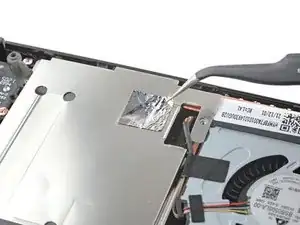
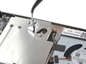
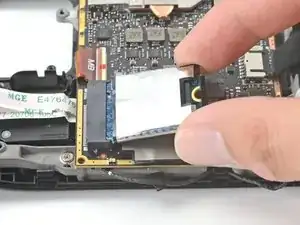
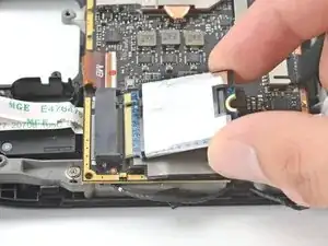
Benutze einen Kreuzschlitzschraubendreher, um die 3,4 mm Schraube zu entfernen, mit der die SSD befestigt ist.
-
-
-
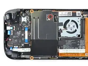
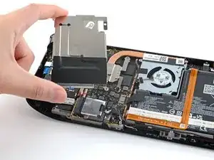
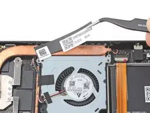
Fasse das Ende der SSD und ziehe sie von ihrem M.2 Platinenstecker weg, um sie zu entfernen.
-
-
-
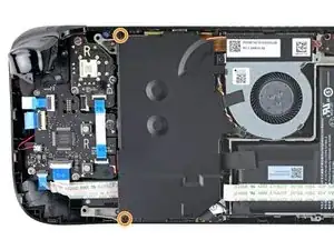
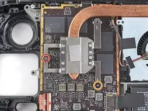
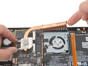
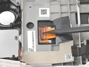
Benutze einen Kreuzschlitzschraubendreher, um die beiden Schrauben zu lösen, mit denen der Kühlkörper am Motherboard befestigt ist:
-
Eine unverlierbare 3,5 mm Schraube
-
Eine 3,4 mm Schraube
-
-
-
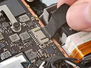
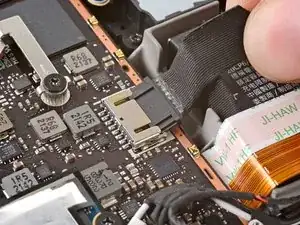
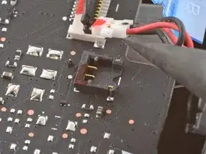
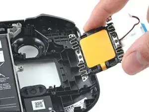
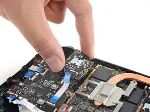
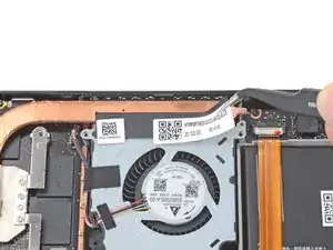
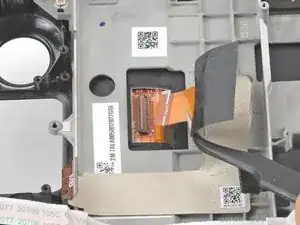
Fasse die Kanten des Lüftersteckers mit einer Pinzette und ziehe ihn hoch, um ihn vom Motherboard abzutrennen.
-
-
-
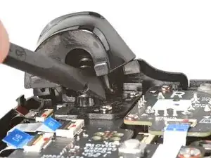
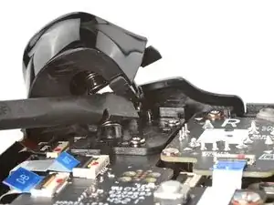
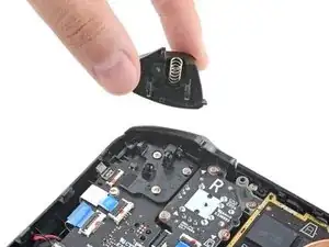
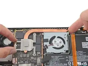
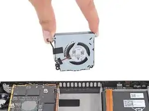
Benutze einen Kreuzschlitzschraubendreher, um die beiden 3,7 mm Schrauben zu entfernen, mit denen der Lüfter befestigt ist.
-
-
-
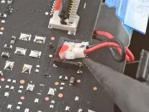
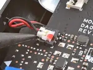
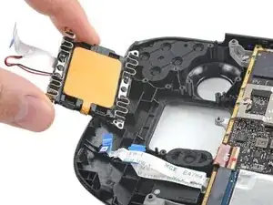
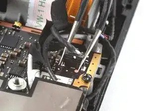
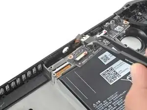
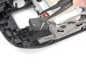
Fasse die Kanten des Lautsprechersteckers mit einer Pinzette und ziehe ihn hoch, um ihn vom Motherboard abzutrennen.
-
-
-
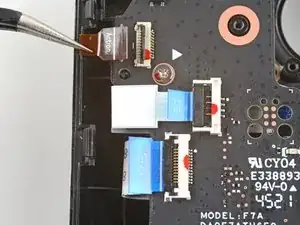
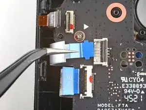
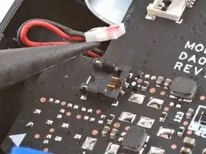
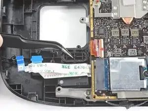
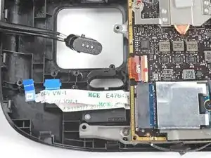
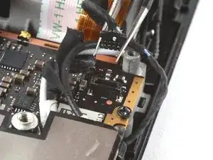
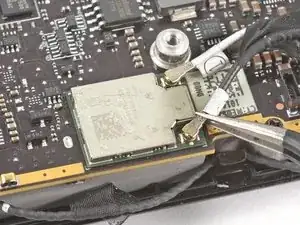
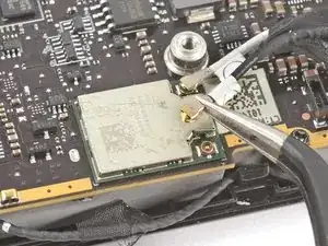
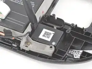
Fasse den Antennen-Stecker ganz unten mit einer Pinzette.
-
Ziehe ihn gerade nach oben, um das Kabel abzutrennen.
-
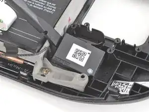
Wiederhole den gleichen Vorgang beim zweiten Antennenkabel.
-
-
-
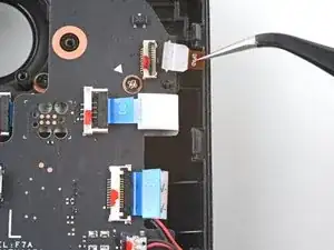
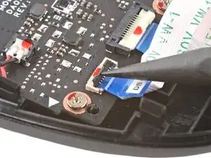
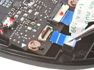
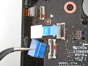
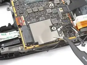
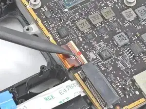
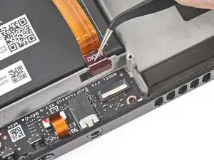
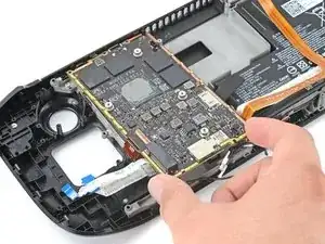
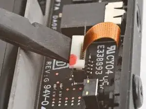
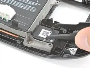
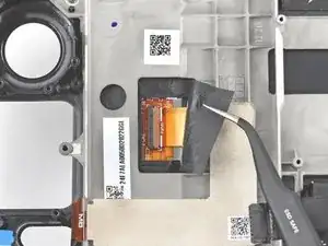
Benutze das spitze Ende eines Spudgers, um den kleinen Sicherungsbügel am ZIF-Verbinder des Displaykabels hochzuheben.
-
Schiebe das Kabel mit einer Pinzette aus seinem Anschluss.
-
-
-
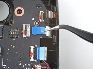
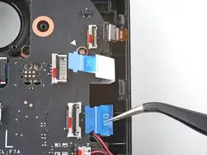
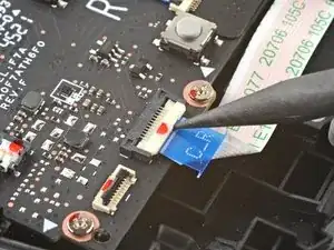
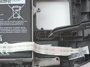
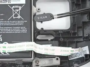
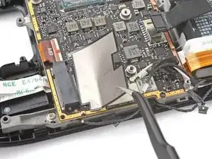
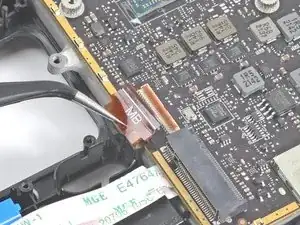
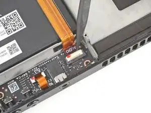
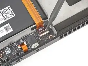
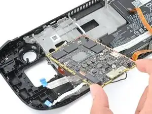
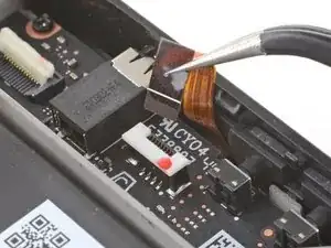
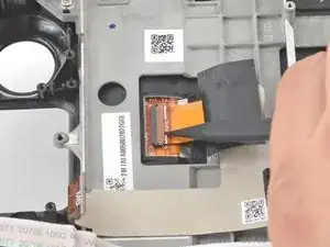
Benutze das spitze Ende eines Spudgers, um den kleinen Sicherungsbügel am ZIF-Verbinder des Audio-Kabels hochzuheben.
-
-
-
Löse das Audio-Kabel vorsichtig vom Akku ab.
-
Falls der Kleber hartnäckig sein sollte, erzwinge es nicht. Erwärme das Audio-Kabel ein wenig mit einem iOpener oder einem Fön, um den Kleber aufzuweichen.
-
-
-
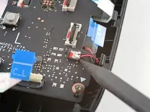
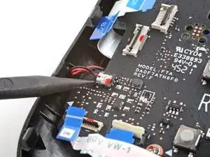
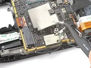
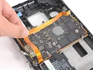
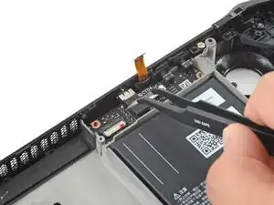
Benutze einen Kreuzschlitzschraubendreher, um die drei 3,7 mm Schrauben zu entfernen, mit denen das Motherboard befestigt ist.
-
-
-
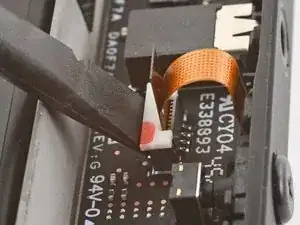
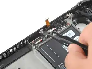
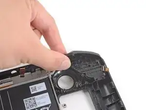
Benutze das spitze Ende eines Spudgers, um den weißen Sicherungsbügel des Mikrofon-Kabels anzuheben.
-
Ziehe das Mikrofonkabel mit einer Pinzette hoch und aus seinem Stecker heraus.
-
-
-
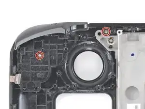
Benutze einen Kreuzschlitzschraubendreher, um die beiden 3,7 mm Schrauben zu entfernen, mit denen die Audio-Platine befestigt ist.
-
-
-
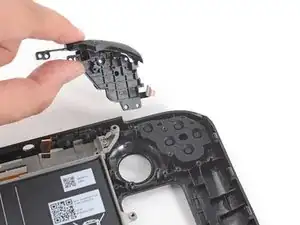
Fasse die Audio-Platine mithilfe einer Pinzette an der Kopfhörerbuchse.
-
Klappe die Platine hoch und aus ihrer Vertiefung heraus, um sie zu entfernen.
-
-
-
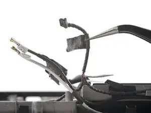
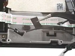
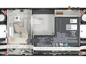
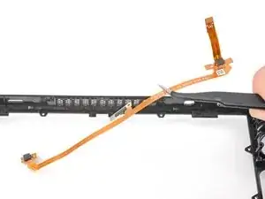
Löse mithilfe einer Pinzette das Klebeband ab, mit dem das Lautsprecherkabel und die WLAN-Antennenkabel zusammengebündelt sind.
-
-
-
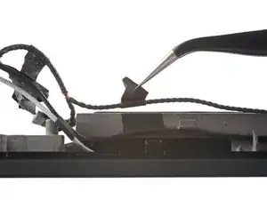
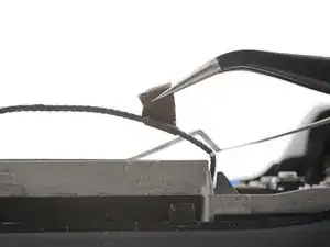
Benutze eine Pinzette, um die verschiedenen Steifen schwarzen Klebebands abzulösen, mit denen das Lautsprecherkabel entlang der Unterkante des Rahmens entlanggeführt wird.
-
-
-
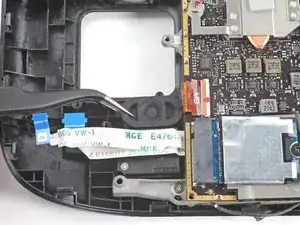
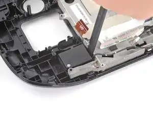
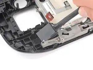
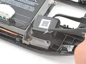
Setze das flache Ende eines Spudgers zwischen den rechten Lautsprecher und den Rahmen.
-
Klappe den Spudger hoch, um den Lautsprecher vom Kleber abzulösen, mit dem er leicht an der Frontabdeckung befestigt ist.
-
-
-
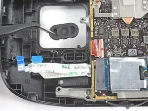
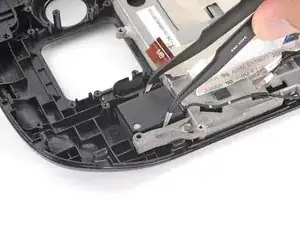
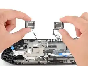
Fasse den Lautsprecher mit einer Pinzette und hole ihn aus seiner Vertiefung heraus, um ihn zu entfernen.
-
-
-
Setze das flache Ende eines Spudgers zwischen den linken Lautsprecher und den Rahmen.
-
Klappe den Spudger hoch, um den Lautsprecher vom Kleber abzulösen, mit dem er leicht an der Frontabdeckung befestigt ist.
-
-
-
Fasse den linken Lautsprecher mit einer Pinzette und hole ihn aus seiner Vertiefung heraus, um ihn zu entfernen.
-
-
-
Hebe den kleinen Sicherungsbügel am ZIF-Verbinder des Displaykabels mit dem spitzen Ende eines Spudgers hoch.
-
Schiebe das Kabel mit einer Pinzette aus seinem Anschluss.
-
-
-
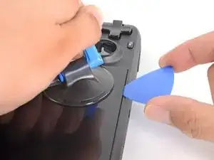
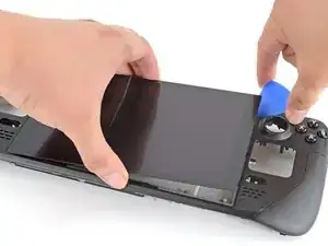
Setze einen Saugheber an der oberen linken Ecke so nahe wie möglich an der Kante auf das Display und drücke ihn fest.
-
Ziehe den Saugheber fest und gleichmässig hoch, bis ein Spalt zwischen Display und Rahmen entsteht.
-
Setze die Spitze eines Plektrum in den Spalt ein.
-
-
-
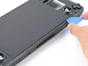
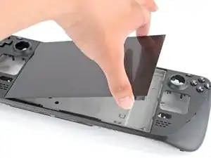
Schiebe das Plektrum an der Oberkante entlang, um den Kleber durchzuschneiden. Die Spitze des Plektrum darf nicht tiefer als 3 mm eingesetzt werden!
-
-
-
Erhitze die linke Kante des Displays eine Minute lang.
-
Schiebe ein Plektrum an der linken Kante entlang, um den Kleber durchzuschneiden.
-
-
-
Wenn du einmal um das ganze Display herum geschnitten hast, hebe die die rechte Kante vorsichtig hoch, wie wenn du ein Buch aufklappst.
-
Entferne das Display.
-
-
-
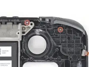
Benutze einen Kreuzschlitzschraubendreher, um die beiden 5,2 mm Schrauben zu entfernen, mit denen die linke Schultertasten-Einheit befestigt ist.
-
-
-
Benutze einen Kreuzschlitzschraubendreher, um die beiden 5,2 mm Schrauben zu entfernen, mit denen die rechte Schultertasten-Einheit befestigt ist.
-
-
-
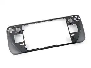
Benutze einen Kreuzschlitzschraubendreher, um die sechs 2,3 mm Schrauben zu entfernen, mit denen der Mittelrahmen an der Frontabdeckung befestigt ist. Sie befinden sich an der Vorderseite.
-
-
-
Benutze einen Kreuzschlitzschraubendreher, um die vier 5,2 mm Schrauben zu entfernen, mit denen der Mittelrahmen an der Frontabdeckung befestigt ist.
-
-
-
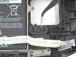
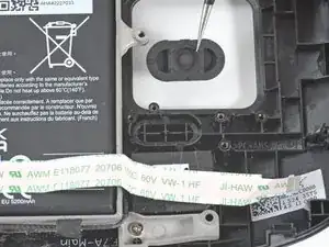
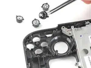
Benutze das spitze Ende eines Spudgers, um die Gummiklappe links von den Lautstärketasten anzuheben und aus ihrem Kunststoffclip zu holen.
-
-
-
Benutze eine Pinzette, um die Lautstärketasten zu entfernen, indem du sie hochhebst und von der Frontabdeckung wegziehst.
-
-
-
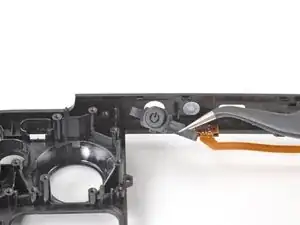
Benutze das spitze Ende eines Spudgers, um die Gummiklappe rechts von der Einschalttaste anzuheben und aus ihrem Kunststoffclip zu holen.
-
-
-
Benutze das spitze Ende eines Spudgers, um die Gummiklappe links von der Einschalttaste anzuheben und aus ihrem Kunststoffclip zu holen.
-
Entferne die Einschalttaste.
-
-
-
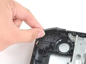
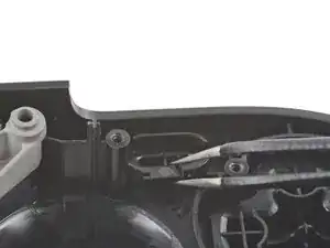
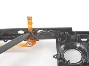
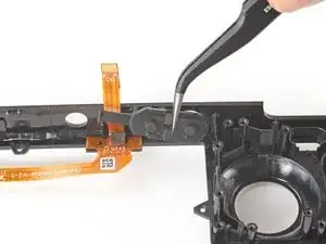
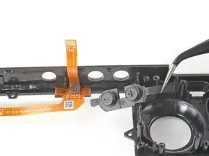
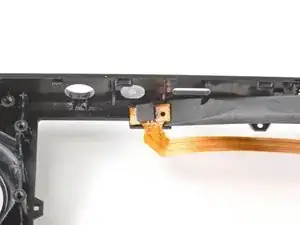
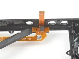
Setze das flache Ende eines Spudgers unter das linke Ende des Mikrofonkabels und heble es hoch, um es von der Frontabdeckung abzulösen.
-
Wenn der Kleber hartnäckig ist, löse das Kabel nicht mit Gewalt ab. Erwärme es leicht mit einem iOpener oder einem Fön, um den Kleber aufzuweichen.
-
-
-
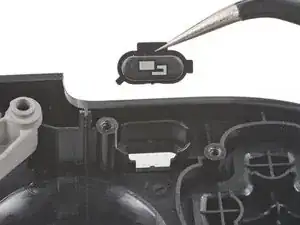
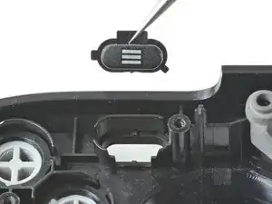
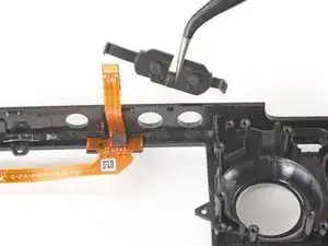
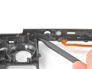
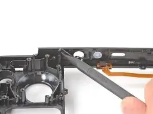
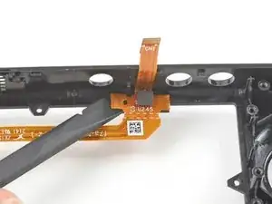
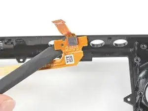
Setze das flache Ende eines Spudgers unter das rechte Ende des Mikrofonkabels und heble es hoch, um es von der Frontabdeckung abzulösen.
-
Wenn der Kleber hartnäckig ist, löse das Kabel nicht mit Gewalt ab. Erwärme es leicht mit einem iOpener oder einem Fön, um den Kleber aufzuweichen.
-


Um dein Gerät wieder zusammenzubauen, folge den Schritten dieser Anleitung in umgekehrter Reihenfolge.
Entsorge deinen Elektromüll fachgerecht.
Lief die Reparatur nicht wie geplant? Versuche es mit einigen grundsätzlichen Lösungsansätzen, ansonsten findest du in unserem Steam Deck Forum Hilfe bei der Fehlersuche.

20 Kommentare
maybe I don’t need an Atomic Purple replacement shell…
Jon -
Hahaha. Same
Rob -
Same, wouldn't have minded a sweet water dipped or translucent outer shell. Bring back that mad catz/third party aesthetic.
I wanted to replace my old shell with a new one cause it got scratches... well, now I feel the scratches ain't that ugly.
Seems to me like a "Welp...I guess if I ever break the screen and have to replace it, that's when I'll get an atomic purple shell...
I dropped mine and scratched it.... This seems to involve more than a simple screen replacement on my phones. I'll likely still order some spare parts just in case. With a baby on the way, they will likely break it and I want to be able to fix it quickly.
Fortunately, mine at the moment works. I should always close the hard case. Took it out of the car and didn't zip it up. Fell right out.
Just fell down the stairs and the joysticks damaged the top shell, but everything still works. After reading this, I think I'm going to live with it. Sheesh.