Einleitung

Diese Anleitung zeigt, wie das Logic Board am Xbox 360 Drahtlos-Controller ausgetauscht wird.

  1. 2n5cabIuJELBKtCp
    2n5cabIuJELBKtCp
    BUPm4PuhYuAFY2QW
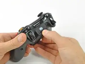
    • Drücke den Knopf am Batteriefach oben am Controller.

    • Entferne das Batteriefach vom Controller.

    • In der normalen Konfiguration verfügt der Xbox 360 Wireless-Controller über AA-Batterien. Eine aufladbare Batterie ist separat erhältlich, aber beide Optionen werden in der gleichen Weise vom Controller entfernt.

  2. pimpfi2dSiLdSctG
    • Benutze eine Pinzette, um den Barcode-Aufkleber aus dem Batteriefach abzulösen.

  3. 2oj6VAsZhlhMMnCo
    • Entferne die sieben 9,3 mm T8 Security Torx Schrauben, welche das rückwärtige Gehäuse an das vordere befestigen.

    Any recommendation on which set of Security Torx tools to use? I've already purchased 2 kits, one of those being sold as "Xbox controller tools" but the diameter of the head does not fit the hole on the controller and that's critical for the 2 screws on the bottom. The tools must obviously be thinner in diameter and long enough to get there.

    Arnie -

    How to open an XBOX 360 controller without a special screwdriver. http://www.instructables.com/id/How-to-o... Works perfectly.

    Louis -

    A lot of thanks for your comment. It's very usefull

    Echedey -

    I picked up a handy torx key set from Auto Zone. Was about $10, no lose driver bits. has both sizes you need to repair the controller and the console. Here's the link:

    http://www.autozone.com/autozone/accesso...

    FierDancr -

    It doesn't really matter which set of bits you by or what brand makes them, Torx bits (and the security versions of them) are generic & come in standardized sizes. You do not need a special "xbox" tool kit, you just need a size 8 torx security bit, no matter what brand makes the bit/kit. Those types of "specialty kits" are usually just collections of generic bits that you can buy at a hardware store in a regular bit set. The difference is that a general bit set will have bits for screws that a specific item doesn't have in it, whereas a specialty kit will only include bits for the types & sizes of fasteners used in the specified item.

    BTW, with the smaller sizes of torx security bits you can try breaking off the little post in the middle with needlenose pliers or something else that can fit in the there. Even if the post doesn't break off cleanly, it's usually short enough to fit a regular (non security) torx bit in the slot.

    Nerfbomb -

  4. 5xJkNxt3DoRVp311
    5xJkNxt3DoRVp311
    fvxUv5tSWmCC3oiH
    • Führe einen Spudger zwischen rückwärtigem und vorderem Gehäuseteil entlang der linken Kante des Controllers ein.

    • Drehe den Spudger in Richtung der Vorderseite des Controllers, um die beiden Gehäuseteile voneinander zu trennen.

  5. Hjf1LBWjF1OCx4jr
    Hjf1LBWjF1OCx4jr
    IUQrUiO6ZuHAHYjg
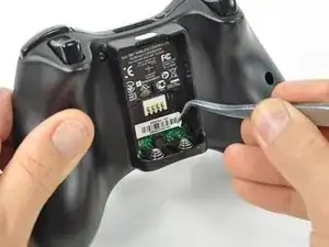
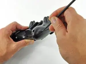
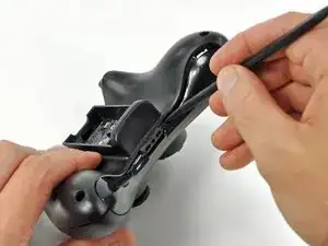
    • Führe einen weiteren Spudger zwischen das rückwärtige und das vordere Gehäuse, nahe des Kopfhöreranschlusses, ein.

    • Drehe den Spudger in Richtung der Vorderseite des Controllers, um die beiden Gehäuseteile voneinander zu trennen.

  6. Oxa5mcnVgNQhStdu
    Oxa5mcnVgNQhStdu
    tB2epfsiXDTCQR4Q
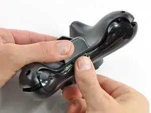
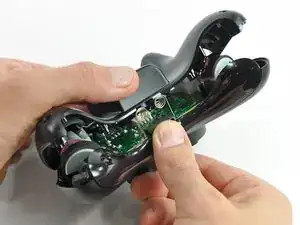
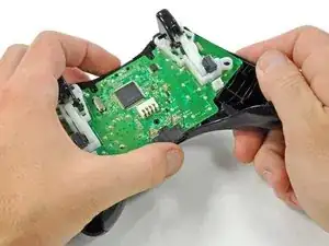
    • Halte den Controller am Batteriefach und am Kopfhöreranschluss.

    • Hebe das Batteriefach weg vom Kopfhöreranschluss und trenne so das rückwärtige Gehäuse vom vorderen Gehäuse sowie dem Logic Board.

    • Die Federn, welche den Kontakt zu den Batterien herstellen, werden durch Slots im Batteriefach an ihrem Platz gehalten. Gehe sicher, dass du diese beim Zusammenbau wieder richtig zusammensteckst!

    The RB / LB bar will fall away easily as you handle the upper case and logic board; just be prepared for it.

    knoxco -

    Good information

    mazvilaa640 -

  7. M2UEQAZJeM5rOiCR
    M2UEQAZJeM5rOiCR
    qaiKdyJ3vSKCYkTc
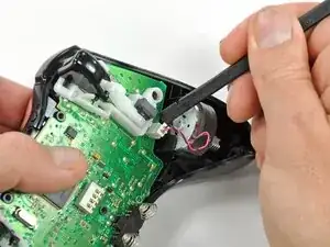
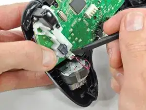
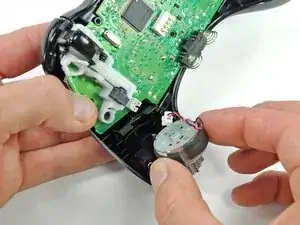
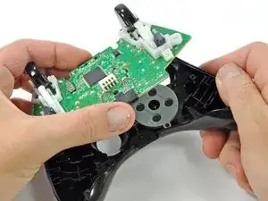
    • Hebe das Kabel des Vibrationsmotors mit dem flachen Ende eines Spudger aus dem Anschluss auf dem Logic Board nach oben und trenne es ab.

    • Hebe den Vibrationsmotor aus dem vorderen Gehäuse heraus.

  8. DwvbBJCujyqTVqaw
    DwvbBJCujyqTVqaw
    xyJQNWVVyfPRslva
    • Entferne auf gleiche Weise den Vibrationsmotor von der anderen Seite des Controllers.

    • Der linke Motor hat deutlich mehr Schwungmasse als der rechte.

    The opposite was true for the controller I just opened. It was the left motor counterweight (as you hold the controller normally) which had more weight. Perhaps it doesn't matter which goes where?

    Bob S -

    For anyone reading this in the future, it does matter. The way you had them originally is the correct way.

    Yado Nada -

  9. VBiVykaL6Mge6Qlf
    VBiVykaL6Mge6Qlf
    cmQQUXvmDOTRL1wK
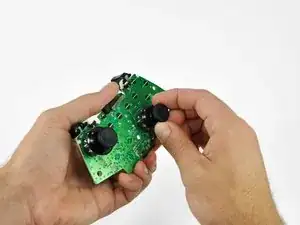
    • Fasse das Logic Board an der Kopfhörerbuchse und Versorgungsbuchse an, hebe es hoch und entferne es vom vorderen Gehäuse.

    What if you're having difficulty taking the logic board out?

    Xander Uchida -

    In my experience with my controller, the logic board lifts out very easily, there are no tabs or fasteners holding it in.

    So, if you're having difficulty taking the logic board out, call a friend with average hand dexterity & motor skills to do it for you.

    Nerfbomb -

    If the controller is a bit old, the center plastic screw holder might have swollen and will need a little stenght to release the logic board.

    RoFixedIt -

  10. aOuEagNlyXCggHDr
    aOuEagNlyXCggHDr
    ChJAnEwSoCMlsQ4t
    • Fasse den rechten Analog-Stick und ziehe die Abdeckung von seinem Befestigungsstift ab.

  11. PSimBC4Ys4GLL1uM
    PSimBC4Ys4GLL1uM
    xivDUNjVklM4TLjV
    • Entferne in gleicher Weise die Abdeckung des linken Analog-Sticks.

  12. LSXN2TCBmIJMBWc4
    LSXN2TCBmIJMBWc4
    1kpisUyfYcsGHTsZ
    IBYXQ1t6MYsQLPwe
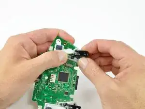
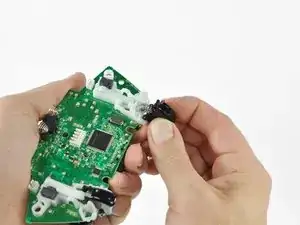
    • Drücke den linken Trigger mit dem Daumen und dem Zeigefinger zur rechten Seite des Controllers hin. Drücke gleichzeitig den Kontrollhebel des Triggers in die entgegengesetzte Richtung.

    • Am Trigger befindet sich ein Stift, der in einen Schlitz im Triggerhebel passt. Achte darauf, dass du weit genug drückst, so dass der Stift aus dem Schlitz herauskommt.

    • Drücke den Triggerhebel nach unten.

  13. LS41yP5KPTDIv5wL
    LS41yP5KPTDIv5wL
    QZ1ioSWoQqIiGWi1
    UmQNVQLLC3xNdeAT
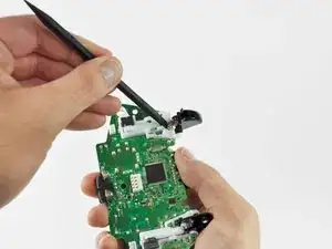
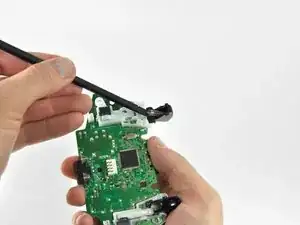
    • Setze die Kante eines Spudgers zwischen den Trigger und die Triggereinheit nahe an der linken Kante ein. Heble die Fassung von ihrer Aufhängung auf dem Trigger weg.

    • Heble in gleicher Weise die Fassung an der rechten Kante vom Trigger weg.

    • Drehe den Trigger vom Logic Board weg und an seiner Fassung vorbei.

  14. 5PVIwMvWMIcEESBI
    5PVIwMvWMIcEESBI
    6uiF3NWB6rDClnlL
    bFumbpPijF5nCVoL
    • Heble mit einem Spudger die Feder im Trigger von ihrem Stift auf der Fassung weg.

    • Ziehe die Feder aus dem Trigger heraus.

  15. 4O1NH31bxPOMsUxu
    4O1NH31bxPOMsUxu
    Zja6UDbWSN6xvXVb
    UxSQ5JbUfSkQliNm
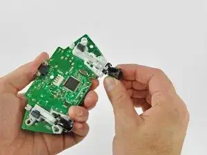
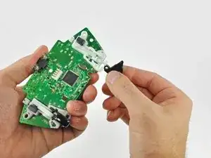
    • Schiebe den Trigger zur rechten Seite des Logic Boards hin und drehe ihn gegen den Uhrzeigersinn.

    • Entferne den rechten Trigger vom Logic Board.

    • Entferne in gleicher Weise den linken Trigger vom Logic Board.

    This is a removal guide not a replacement guide. I need steps to putting the trigger back in now.

    Paul de Boer -

    My trigger works by moving in and out but it is constantly either working or constantly not, when i press the home screen it switches between the two……help please

    Daunte Mooney -

Abschluss

Um dein Gerät wieder zusammenzubauen, folge den Schritten in umgekehrter Reihenfolge.

Brett Hartt

Mitglied seit: 13/04/10

130320 Reputation

8 Kommentare

Does it matter which side the motors are returned to? I think I may have swapped positions with my two motors.

brian -

Any guides for troubleshooting the test points on the board as to determine why the left trigger doesn't aim during gameplay? I've replaced the potentiometer with a brand new one but still nothing, everything else works perfectly …thoughts?

BURNHOT ROBINSON -

bad connection down the Vdc supply, gnd, or sense pin paths? Or a blown channel on the ADC that reads the potentiometer and converts the value to digital. If the ADC is integrated inside the main chip, its toast. Its also possible another component along the signal path may be faulty. Like a capacitor gone short for some reason. Basically its break out the multimeter and start poking stuff time.

Tank R -

I don't need a removal guide I need a diagram that shows me how to put the trigger on a button on top so a child with deformed fingers can use it. The triggers apparently have hall type sensors.

jim27601 -

I havent been inside my official remote yet, but if the unofficial ones Ive scrapped and/or repaired are any indication the triggers are potentiometers, not hall effect sensors. If you're fine with simple binary control (ie, on off, and not the analog sweep of values) then just wire the center pad and what ever side the wiper moves towards (whichever side drops in resistance when going to full deflection) to a button. If that doesnt work, try center and the other pin.

Tank R -

The logic board won't come out, and I don't want to force it out. Any ideas on how to take it out?

Xander Uchida -

Any guide to checking traces and components on the circuit board for the radio frequency crystal and antenna as have a controller that does not sync though powers on and light cycles correctly after sync button is pressed

Answer42 -

Algun tutorial para reparar el Star del mando ya cambié membrana y sigue con el fallo, cabe mencionar que lo e limpiado con isopropílico y tampoco

Trejo Jorge -